Table of Contents
Advertisement
Quick Links
Advertisement
Table of Contents

Related Manuals for WEIGL ProCommander ES


Summary of Contents for WEIGL ProCommander ES
- Page 2 +43 (0) 650 84 333 48 www.Weigl-EM.at Office@Weigl-EM.at Weigl-EM is the hardware manufacturer and European distributor Weigl Works, LLC 440-941-5849 www.WeiglWorks.com Info@WeiglWorks.com Weigl Works, LLC is the exclusive North American distributor of Weigl-EM products © 2013 - Weigl – Elektronik & Mediaprojekte...
-
Page 3: Table Of Contents
1.3 FCC DECLARATION OF CONFORMITY ........ 9 1.4 CE DECLARATION OF CONFORMITY ........ 10 2 Warranty ................13 3 ProCommander ES PIN ASSIGNMENTS ......... 15 3.1 ProCommander ES FRONT ..........15 3.1.1 Pin Assignments FRONT ........... 15 3.2 ProCommander ES BACK ..........17 3.2.1 Pin assignment for Open-Collector Circuit.... - Page 4 !v: Variable events ............39 8 Playlist functions ..............43 9 Folder structure of the Flash Card .........45 10 Programming the ProCommander ES ........47 11 Network connection between ProCommander ES and Pro I/O ....................49 12 Interface protocols ..............53 13 Appendix ................55 13.1 Pin assignment DMX-OUT ..........55 13.2 Assignment Remote 1-8, Open-Collector 1-8 ....56...
-
Page 5: Important Information And Safety Tips
Important Information and Safety Tips 1 Important Information and Safety Tips The ProCommander ES is an electronic device that can fail, in part or in full despite careful testing. Therefore, it must not be used in applications where personal safety could be at risk due to the malfunction of the device. - Page 6 In addition, correct polarity must be utilized to avoid damage to the ProCommander ES. Failure to do so will void the warranty and Weigl Works, LLC or Weigl will not be liable for any resulting damages. When connecting solenoids, a freewheeling diode for each solenoid is required.
-
Page 7: Fcc And Ce Compliance
The ProCommander ES is low voltage DC devices and therefore, neither UL nor CE require safety testing. For fireproofing or additional radio frequency interference shielding, the ProCommander ES can be rack mounted in a 19" rack space 1.2 FCC Instruction to User with optional hardware. - Page 8 Important Information and Safety Tips Consult the dealer or an experienced radio/TV technician for help. This equipment has been verified to comply with the limits for a class B computing device, pursuant to FCC Rules. In order to maintain compliance with FCC regulations, shielded cables must be used with this equipment.
-
Page 9: Fcc Declaration Of Conformity
Entertainment and Lighting Control Equipment Class: Commercial Light Industrial Model: Weigl ProCommander ES Year of Manufacture: 2012 I the undersigned, hereby declare that the equipment specified above conforms to the above directive(s) and standard(s). Place: Gramastetten, Date: May 23 , 2013... -
Page 10: Ce Declaration Of Conformity
1.4 CE DECLARATION OF CONFORMITY Important Information and Safety Tips Weigl ProCommander ES have been tested to comply with CE requirements. Model: Weigl ProCommander ES This product herewith confirmed to comply with the requirements set out in the Council Directive on the approximation of the laws of the Member States relating to Electromagnetic Compatibility Directive 2004/108/EG. - Page 11 Important Information and Safety Tips I the undersigned, hereby declare that the equipment specified above conforms to the above directive(s) and standard(s). Place: Gramastetten, Date: May 23 , 2013 Full Name: Manfred Weigl...
- Page 12 Important Information and Safety Tips...
-
Page 13: Warranty
The customer will pay all shipping costs to and from Weigl Works, LLC or Weigl should parts be repaired or replaced in the ProCommander ES. The transport of the ProCommander is at the risk of the customer. - Page 14 Warranty By not following the instructions (i.e. connection to the wrong voltage or incorrect input or output circuit) Damage caused by negligent handling, misuse, or improper use of ProCommander ES.
-
Page 15: Procommander Es Pin Assignments
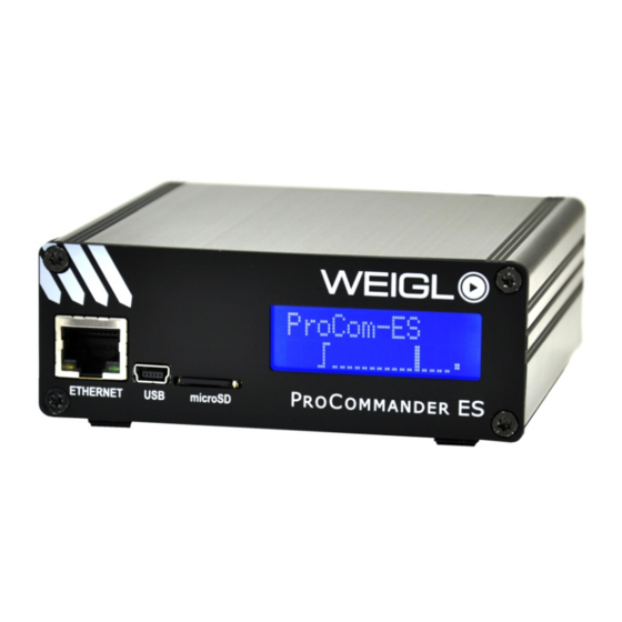
3.1.1 Pin Assignments FRONT ETHERNET The network port can be used for programming and configuration. Through the USB port you can configure or update the ProCommander ES. Please make sure that you have installed the applicable driver. download them from... - Page 16 ProCommander ES pin assignments http://www.weigl-em.at/en/download. Further information for installation you can find here 4 USB – driver installation. microSD Slot for the microSD card. Before plug in or removing a microSD card, switching OFF the unit. To plug in the card, push the card until it is flush with the front panel.
-
Page 17: Procommander Es Back
3.2.1 Pin assignment for Open-Collector Circuit POWER The ProCommander ES can be operated with voltages from 12V to 24V. The 24V may not be exceeded in any case. Thus, if the power supply has a ripple in the voltage, the peak voltage must not exceed 24V. - Page 18 The maximum current per output must not exceed 2A. LINE OUT An external audio amplifier can be connected to the line-out outputs of the ProCommander ES. A parallel operation with the internal amplifier is possible under certain conditions, and...
- Page 19 If necessary, the function must be proven if it works properly. LS-OUT The ProCommander ES has a built in 2x20W Class D amplifier. At the two outputs LS-L (left channel) and LS-R (right channel), either 4-ohm or 8-ohm speakers may be connected.
- Page 20 ProCommander ES pin assignments Supply- and GND-Pins Schematic for output connection: On pin 9 of the 10-pin connector blocks the internal voltage of the power supply is brought out. Pin 9 of the top row is permanently connected. Pin 9 of the bottom row is connected to the common cathode of the output driver.
- Page 21 ProCommander ES pin assignments Jumper open Jumper closed The maximum total current depends on the used power supply, but must not exceed 500mA. For proper functions of the ProCommander ES if the audio amplifier is used, a current...
- Page 22 ProCommander ES pin assignments consumption of about 1 ampere must be calculated. To ensure proper function of the ProCommander ES, when using the supplied power must be part of the load is not more than 200mA. The voltage is dependent on the power supply unit minus the voltage loss of internal reverse polarity protection diode.
-
Page 23: Usb - Driver Installation
USB – driver installation 4 USB – driver installation As soon as the ProCommander ES is connected to your computer, Windows automatically search for the appropriate driver software. When you see this dialog box, select "Browse my computer for driver software". - Page 24 USB – driver installation If you receive the following security warning, confirm with "Install this driver software anyway".
- Page 25 USB – driver installation Then the driver software is installed. If the driver software has been installed successfully, the following dialog box will appear:...
- Page 26 USB – driver installation If you later want to elicit the COM-port, you will find this under "Control Panel" → "Device Manager" → "Ports (COM&LPT)".
-
Page 27: Procommander Es Configuration
USB or commands from a microSD card while operating. You can configure the ProCommander ES via USB through a terminal program, if the USB driver for the ProCommander ES is correctly installed on your PC, a COM port will be activated when you connect them. - Page 28 ProCommander ES configuration You do not have to install the program. Copy the file from the zip-archive into a new folder and start WemcConfig.exe with double-click. After starting this window appears: Press the button "Scan for Devices" and the connected device...
- Page 29 With the button "Save Permanently" the new parameters are stored permanently on the ProCommander ES. By clicking "Save Temporarily" the new settings will be temporarily stored, when the device is switched off and on again, the original stored values...
- Page 30 10.0.0.101, and the subnet mask is 255.255.255.0. To connect your computer with the ProCommander ES you have to change the network settings. For this purpose you open the network properties through the control panel. Chose the internet protocol version 4 and press the button...
-
Page 31: Firmware Update
With the button "FW Update Network" you can record the ProCommander ES with the latest operating software. Connect the ProCommander ES to the network interface of the computer. Start the configurator and search with the button "Scan for Devices" for the connected ProCommander ES and... - Page 32 "ProComES_Vxxx.hex" file. The data "Vxxx" corresponds to the latest version of the ProComES.hex-file. This will be transferred to the ProCommander ES. Attention: During this process do not close the configurator and do not shut down the device! As an indicator for proper update procedure, you see in the...
- Page 33 ProCommander ES configuration...
- Page 34 ProCommander ES configuration Meanwhile you can see on the display of the ProCommander "P's", which are running from the left to the right. As soon as the update was successful, "ProCom" appears on the display. And the dialog "Firmware update complete!" will be...
-
Page 35: Variable
Variable 6 Variable With variables decisions can be made, conditional show starts or counter can be realized. Variables can be manipulated inside a show or through external events. Possible actions are setting a value of a variable or executing mathematical operations like add, subtract, multiply or divide. - Page 36 Variable...
-
Page 37: Control.ini
Control.ini 7 Control.ini The "Control.ini" file is a new and easy way to assign different input events to any of the available ASCII-commands without any special show programming. It is even possible to assign an input event to several successive commands. An input event may be a change of the remote inputs, a time event or a variable change. -
Page 38: I: Event Related To The Remote Inputs 1-16
Control.ini !i: Event related to the remote inputs 1-16 Example: !i1c# → if input 1 is activated (c=close). !i1o# → if input 1 is deactivated (o=open). !i1t# → if input 1 changes (t=toggle). !t: Time events The internal timer of the clock starts counting with zero seconds, zero minutes and zero hours at the moment the device is powered up. -
Page 39: V: Variable Events
Control.ini &05:00 means, that all 5 minutes the downstream command will be executed. c is the signal for external clock. So if an external clock is connected, the specified value is compared to this clock. Example: !tm01:20# → if the time reached 1 minute 20 seconds after the start-up or plug in of the card, then the following command will be executed. - Page 40 Control.ini Example: !ess1001# → the open collector outputs 1 and 4 will be set (see ASCII-protocol). With the combination of the input event, it looks like this: !i1c!ess1001# You can assign several commands to an input event. In this case, attach the additional commands. The total number of characters of a command line must not exceed 150 characters.
- Page 41 Control.ini The content of the Control.ini file can look like this: !i1c!ess1001!edv10:255# !i5c!cfm0<5# !i5o!cfm32<5# !tm01:20!rsn:\SHOW\001_SHOW.WM1# !t&05:00!rsn:2# line: if input 1 is closed, the open collector outputs 1 and 4 will be activated and additionally the channel 10 will be set to 255.
- Page 42 Control.ini For the various commands and features, please download the ASCII-chart.
-
Page 43: Playlist Functions
Playlist functions 8 Playlist functions Audio files for the ProCommander ES must be OGG Vorbis format. For converting audio formats to OGG Vorbis, seek appropriate software. Both ConductorPro and VenueMagic software automatically generate OGG Vorbis files. The ProCommander ES can manage multiple playlists. The playlists are stored in the folder called PLAYLxxx. - Page 44 Playlist functions playing because of a playlist function, or a show has started the track. This command affects only the soundtrack and does not affect a possible running show. !psc# is the command to continue a paused soundtrack.
-
Page 45: Folder Structure Of The Flash Card
Folder structure of the Flash Card 9 Folder structure of the Flash Card To begin shows, audio files, or respectively playlists, folder and file names have to follow a predefined order. Generally, only one subdirectory is supported. All shows must therefore be in the "SHOWS" folder. The first three characters of the show name must have a number in the range of 001-999. - Page 46 Folder structure of the Flash Card...
-
Page 47: Programming The Procommander Es
Programming the ProCommander ES 10 Programming the ProCommander ES Due to the open interface protocol, there are various software programs that support the ProCommander ES. Please refer to the manual of the respective software to learn how to program the ProCommander ES. - Page 48 Programming the ProCommander ES...
-
Page 49: Network Connection Between Procommander Es And Pro I/O
Network connection between ProCommander ES and Pro I/O 11 Network connection between ProCommander ES and Pro I/O The ProCommander ES commands an intern chart, which associate each Sub-Device-ID of a Pro I/O module with an address. By default for all modules broadcast addresses are adjusted,... - Page 50 Example: Sub-Device-ID address address 192.168.10.201# is chosen. The command reads as followed !swi192.168.10.201#. It assigns automatically IP addresses in ascending order for all 32 possible modules on the ProCommander ES. With the command !gpa# the intern chart can be called.
- Page 51 Network connection between ProCommander ES and Pro I/O In this case the result looks like this: Now, all IP addresses of the Pro I/O modules have to be modified in accordance with the chart above. So, module with A1 on the display gets 192.168.10.201, with A2 on the display gets 192.168.10.202 etc.
- Page 52 Network connection between ProCommander ES and Pro I/O Example: For the second ProCommander the first Pro I/O module will be assigned with the IP address 192.168.10.241 with the command !swi192.168.10.241#. With the command !gpa# the intern chart will be called, these looks like this:...
-
Page 53: Interface Protocols
Interface protocols 12 Interface protocols The ProCommander ES can be controlled in a variety of ways. To allow a broad range of applications to control the ProCommander ES, an easy-to-understand and simple-to-handle ASCII-protocol has been introduced. In addition, there is an open HEX protocol designed for short commands. - Page 54 Interface protocols...
-
Page 55: Appendix
Appendix 13 Appendix 13.1 Pin assignment DMX-OUT Connector Function Pin 1 Pin 2 DMX-OUT - Pin 3 DMX-OUT + N.C. = not connected. -
Page 56: Assignment Remote 1-8, Open-Collector 1-8
13.2 Assignment Remote 1-8, Open-Collector 1-8 Appendix Remote 1-8/ Open-Collector 1-8 Connector Upper row Lower row Input 1 Open-Collector 1 Input 2 Open-Collector 2 Input 3 Open-Collector 3 Input 4 Open-Collector 4 Input 5 Open-Collector 5 Input 6 Open-Collector 6 Input 7 Open-Collector 7 Input 8... -
Page 57: Pin Assignment Ls (Loudspeaker)
13.3 Pin assignment LS (Loudspeaker) Appendix Connector Function Pin 1 Left + Pin 2 Pin 3 Right + Pin 4... - Page 58 Appendix...
-
Page 59: Glossary
Glossary 14 Glossary Sub-Device-ID Device address. Each device has its own device address it is required to issue commands, which are sent to a device to be correctly handled. - Page 60 Glossary...
-
Page 61: Index
ETHERNET ........ 15 microSD ........16 FCC and CE Compliance ....7 FCC DECLARATION OF Network connection between CONFORMITY......9 ProCommander ES and Pro I/O FCC Instruction to User ....7 ..........49 Folder structure of the Flash Card ........... 45... - Page 62 Index OPEN-COLLECTOR 1-8....18 Supply- and GND-Pins ....20 Pin assignment USB .......... 15 DMX-OUT ......55 USB – driver installation .... 23 LS (Loudspeaker) ....57 Open-Collector 1-8 ....56 Remote 1-8......56 PIN ASSIGNMENT ..... 15 Variable ........35 BACK ........
Need help?
Do you have a question about the ProCommander ES and is the answer not in the manual?
Questions and answers