Table of Contents
Advertisement
Advertisement
Table of Contents

Related Manuals for Newport New Focus Picomotor 8742


Summary of Contents for Newport New Focus Picomotor 8742
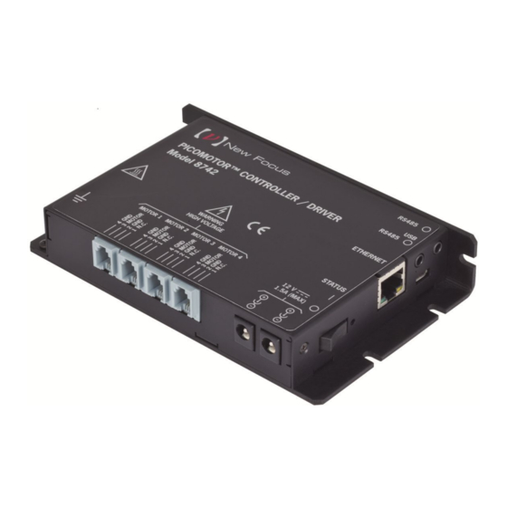
- Page 1 Model 8742 Picomotor™ Controller/Driver User’s Manual...
-
Page 2: Eu27 Declaration Of Conformity
Preface EU27 DECLARATION OF CONFORMITY Application of Council Directive(s): ☒ Electromagnetic Compatibility Directive (EMCD) – 2014/30/EU ☒ Low Voltage Directive (LVD) – 2014/35/EU ☒ Restriction of Hazardous Substances Directive (RoHS2) – 2011/65/EU ☒ Restriction of Hazardous Substances Directive (RoHS3) – (EU) 2015/863 ☒... -
Page 3: Uk Declaration Of Conformity
Preface UK DECLARATION OF CONFORMITY Application of Council Directive(s): ☒ Electromagnetic Compatibility Directive (EMCD) – 2014/30/EU ☒ Low Voltage Directive (LVD) – 2014/35/EU ☒ Restriction of Hazardous Substances Directive (RoHS2) – 2011/65/EU ☒ Restriction of Hazardous Substances Directive (RoHS3) – (EU) 2015/863 ☒... -
Page 4: Warranty
Focus's option. To exercise this warranty, write or call your local New Focus office or representative, or contact Newport headquarters in Irvine, California. You will be given prompt assistance and return instructions. Send the product, freight prepaid, to the indicated service facility. Repairs will be made and the instrument returned freight prepaid. - Page 5 Programs; or (4) approved by New Focus for release without restriction. Trademarks The New Focus logo and name are registered trademarks of Newport Corporation in Mexico, Israel, Singapore, European Union, Taiwan, Hong Kong, China, Japan, Korea, Canada, Australia, and the United States.
-
Page 6: Technical Support Contacts
Newport Corporation, freight prepaid, clearly marked with the RMA# and we will either repair or replace it at our discretion. Newport is not responsible for damage occurring in transit and is not obligated to accept products returned without an RMA#. -
Page 7: Table Of Contents
Preface Table of Contents EU27 DECLARATION OF CONFORMITY ........ii UK DECLARATION OF CONFORMITY .......... iii Warranty ....................iv Technical Support Contacts ..............vi Table of Contents ................. vii List of Figures ..................x Safety Precautions Definitions and Symbols .............11 1.1.1 General Warning or Caution ...........11 1.1.2 Electric Shock ..............11 1.1.3 Potential Burn Hazard .............11 1.1.4 European Union CE Mark ..........12... - Page 8 viii Preface 2.6.1 Operating Limits* ............24 2.6.2 Weight, Dimensions ............25 Theory of Operation How the Picomotor Actuator Works ...........26 Stepping the Picomotor with the 8742 Controller/Driver ...26 Status Indicator ................27 Power Supply ................28 3.4.1 Fault Protection ...............28 Input / Output Connections ............29 3.5.1 USB .................30 3.5.2 Ethernet ................30 3.5.3 RS-485 ................30...
- Page 9 Preface 5.4.2 Using a Static IP Address ..........43 5.4.3 Ethernet Peer-to-Peer Cabling .........46 5.4.4 Communicating Using a Hostname .........46 RS-485 Communication ..............47 5.5.1 Setting up an RS-485 Network ........48 5.5.2 Communication with a Slave Controller ......49 Picomotor Controller Software Application ........50 5.6.1 Introduction ..............50 5.6.2 Overview .................51 5.6.3 Embedded Dynamic HTTP Server ........62...
-
Page 10: List Of Figures
Preface List of Figures General Warning or Caution Symbol ........... 11 Electrical Shock Symbol ............... 11 Hot Surface Symbol ..............11 CE Mark ..................12 UKCA Mark.................. 12 Alternating Voltage Symbol ............12 On Symbol ..................12 Off Symbol..................12 Ground Symbol ................ -
Page 11: Safety Precautions
Safety Precautions Definitions and Symbols The following terms and symbols are used in this documentation and also appear on the Model 8742 Controller/Driver where safety-related issues occur. 1.1.1 General Warning or Caution General Warning or Caution Symbol The Exclamation Symbol in the figure above appears on the product and in Warning and Caution tables throughout this document. -
Page 12: European Union Ce Mark
Safety Precautions 1.1.4 European Union CE Mark CE Mark The presence of the CE Mark on New Focus equipment means that this instrument has been designed, tested and certified compliant to all applicable European Union (CE) regulations and recommendations. 1.1.5 UKCA Mark UKCA Mark The presence of the UKCA Mark on New Focus equipment means that this... -
Page 13: Ground
Safety Precautions 1.1.9 Ground Ground Symbol The symbol in the figure above appears on the Model 8742 to indicate the screw to be used to ground the case of the unit. This symbol identifies the frame or chassis terminal. 1.1.10 DC Symbol DC Symbol This international symbol implies an unvarying current or voltage. -
Page 14: Warnings And Cautions
Safety Precautions Warnings and Cautions The Model 8742 is a component of a system that will contain one or more Picomotors and other items. Since New Focus cannot control these other system components, the User is ultimately responsible for ensuring that the complete system meets all applicable product and workplace safety regulations. -
Page 15: General Cautions
Safety Precautions • The Model 8742 is typically supplied with an external DC power source. When the external power source is connected to MAINS power, the external power source’s detachable power cord may be used to disconnect power to the 8742. Do not position the external power supply so that its MAINS power cord cannot be easily disconnected. - Page 16 Safety Precautions WARNING The Model 8742 Picomotor Controller/Driver internally generates non-SELV voltages. These voltages are present, at times, on the Picomotor connectors even when a Picomotor is not connected. The user shall mount the Model 8742 with appropriate barriers, spacings, markings, etc. to ensure that all applicable regulatory requirements are met.
- Page 17 Safety Precautions CAUTION There are no user serviceable parts inside the Model 8742 Picomotor Controller/Driver. Work performed by persons not authorized by New Focus will void the warranty. WARNING If this equipment is used in a manner not specified in this manual, the protection provided by this equipment may be impaired.
-
Page 18: Location Of Labels And Warnings
Safety Precautions The Model 8742 Picomotor Controller/Driver is intended for use in an industrial laboratory environment. Use of this product in other environments, such as residential, may result in electromagnetic compatibility difficulties due to conducted as well as radiated disturbances. The Model 8742 Picomotor Controller/Driver is intended for use in an industrial laboratory environment. -
Page 19: Safety Grounding Considerations
Safety Precautions Safety Grounding Considerations There are potentially lethal voltages generated within the Model 8742 Picomotor Controller/Driver and presented on the pins of the “Motor” connectors EVEN WHEN NO PICOMOTOR IS INSTALLED. (These voltages are not present when power is not applied to the unit. They are not present when the unit is switched OFF.) The User must manage certain system-level aspects to ensure safe operation. - Page 20 Safety Precautions because this insulation will probably need to have a breakdown voltage of several thousand volts due to lightening concerns. In summary, New Focus strongly recommends grounding the Model 8742’s case.
-
Page 21: General Information
General Information System Overview 8742 is a 4-axis open-loop motion controller/driver for Picomotors, offering a complete motion solution for many applications. It can control up to 4 Picomotors and it can work in systems with other Model 8742 and 8743-CL Controller/Drivers to drive a large number of Picomotors. -
Page 22: Scope Of This Manual
General Information Scope of this Manual Please carefully read this instruction manual before using the 8742 Picomotor Controller/Driver. Be especially careful to observe the warnings and cautions throughout this manual (see Safety Symbols and Terms). If any operating instructions are not clear, contact New Focus. This instruction manual contains the necessary information for operation and maintenance of the Model 8742, as well as information for troubleshooting and obtaining service if necessary. -
Page 23: Safety
General Information Safety Voltages of up to 130 V are accessible inside the 8742 Controller/Driver chassis, mounts, and Picomotors. DO NOT operate the units with the driver or mount covers removed. If the wire of a mount or Picomotor is damaged, discontinue use and return it for repair. -
Page 24: Specifications
General Information Specifications 2.6.1 Operating Limits* PARAMETER MIN. MAX. Model 8742 Power input voltage (+V IN) 10.5 V 14.5 V 11 Watts 2 Watts Power Consumption @ 12 Volts (@ 2 kHz (Idle) speed) Ambient still-air operating temperature 0 °C 65 °C Storage temperature (non-operating) -40 °C... -
Page 25: Weight, Dimensions
2.6.2 Weight, Dimensions Weight 9.5 oz (270 g) (L x W x H) Dimensions 5.84 in x 3.61 in x 1.02 in 148.3 mm x 91.7 mm x 25.9 mm... -
Page 26: Theory Of Operation
Theory of Operation How the Picomotor Actuator Works The patented design of the Picomotor actuator relies on the basic difference between dynamic and static friction. A graphic example of this is the “tablecloth trick”, in which a quick pull of the cloth leaves the dishes on the table, while a slow pull of the tablecloth ends up pulling the dishes off the table (high static friction). -
Page 27: Status Indicator
Theory of Operation Status Indicator The LED located near the power switch has several functions: Power Indicator • • Status Indicator Troubleshooter • Status Indicator Power Switch Status Indicators position When the unit is turned on the unit goes through a series of verifications and turns the LED solid green. -
Page 28: Power Supply
Theory of Operation Power Supply The 8742 Controller/Driver can place stress on the system power supply. The stress has two components: Inrush current: The inrush current on power-up charges the internal filter capacitor. While the energy magnitude of the inrush current is limited, it can still cause problems with power supplies not designed to handle it. -
Page 29: Input / Output Connections
Theory of Operation A heatsink can be mounted using these slots Heatsink mounting slots Input / Output Connections Figure 14 shows the 8742 input and output connections. Communication Interfaces: USB, Ethernet, RS-485 (2) Power Inputs: +12VDC (2) Picomotor Interfaces: 4 The following figure shows the position of the inputs and outputs as well as the power switch. -
Page 30: Usb
Theory of Operation 3.5.1 The USB input is a Micro-AB connector. Use a Micro-B to USB-A cable to connect the 8742 Controller/Driver to a computer. 3.5.2 Ethernet The Ethernet input is a standard RJ-45 connector. Use a Cat 5 Ethernet cable to connect the 8742 Controller/Driver to a router, an Ethernet switch, or a computer. -
Page 31: Mounting The Unit
Theory of Operation Mounting the unit 8742 may be set on a table top. While not required, the 8742 can be bolted to the table top in either horizontal or vertical orientation. Under conditions of extreme usage, the case temperature of the Model 8742 may exceed the levels considered safe by various international safety conventions. -
Page 32: Initial Setup
Initial Setup Introduction This section contains information on how to connect the 8742 Controller/Driver to your local line voltage and how to connect the Picomotor to the controller. It also includes a discussion about the remote interface and the instrument’s power-up. Grounding Connect the 8-32 grounding screw to a good earth ground using a dedicated wire of at least 20AWG diameter. -
Page 33: Connecting 8742 To A Computer Via Ethernet
Initial Setup Connecting 8742 to a Computer via Ethernet 4.5.1 Connecting to a Router The 8742 Controller/Driver can be connected to an Ethernet Router. Attach the computer Ethernet cable to the same router. If desired, the router can be attached to a WAN (Wide Area Network) so that the computer can also be connected to internet, or company network. -
Page 34: Connecting Multiple Units To A Computer
Initial Setup Connecting Multiple Units to a Computer The L-bracket (Figure 16) is an optional accessory to stack up several 8742 or 8743- CL units. The stack is shown in Figure 17. L-bracket Using L-brackets to stack up several Controllers... -
Page 35: Using Usb Hubs
Initial Setup 4.7.1 Using USB Hubs Each 8742 Controller/Driver in the stack can be connected to a USB hub. Connect the hub to a computer and launch the Picomotor Application provided on the USB Flash Drive. The application will automatically discover and display the 8742 units and make them available for control. -
Page 36: Using Ethernet Routers/Switchers
Initial Setup 4.7.2 Using Ethernet Routers/Switchers If several 8742 units need to be controlled via Ethernet, connect them to a router at the LAN (Local Area Network) ports. The router will assign an IP address to each 8742 Controller/Driver. Connect a computer to the same router at one LAN port. Use the Picomotor Application provided on the USB Flash Drive to discover and establish a connection to each 8742 unit. -
Page 37: Using Rs-485 Lan To Daisy-Chain
Initial Setup 4.7.3 Using RS-485 LAN to Daisy-Chain If several 8742 units need to be controlled via Ethernet or USB, they do not all have to be connected directly to an Ethernet Switch or USB Hub. Instead, a single unit can act as a gateway by connecting it to the Router, Switch, or Hub and also connecting it to the remaining units using a half-duplex RS-485 LAN bus. - Page 38 Initial Setup This product’s RS-485 LAN implementation is a multidrop, half-duplex, 2-wire, differential signaling, balanced line over twisted pair setup. Hence, 1.2 km (~4K feet) distance is theoretically possible. Note that it is possible to use an off-the-shelf third party RS-485 converter/adapter to connect into the controller’s RS-485 LAN as an alternative to USB or Ethernet connectivity.
-
Page 39: Connecting To The 8758 Hand Control Pad
Initial Setup Connecting to the 8758 Hand Control Pad The model 8758 hand control pad facilitates local (non-computer) control of positioners connected to 8742 Picomotor controllers. It draws its electrical power from the Picomotor controller via USB interface and, hence, does not require a separate power supply. IMPORTANT: 8742 controller must run firmware version 2.2 (or later) to be compatible with the 8758 hand control pad. -
Page 40: Multiple Controller Setup
Initial Setup The 8758 hand control pad is capable of interfacing with up to 31 Picomotor controllers when configured in the RS-485 daisy-chained “Master/Slave” setup shown below. The controller that has the 8758 connected to it automatically becomes the designated Master Controller. -
Page 41: Computer Interfacing
Computer Interfacing Introduction The Model 8742 Controller/Driver has two computer interface ports: USB-Device and Ethernet. All commands for the 8742 Controller/Driver are device dependent commands. Please see the General Guidelines sections for using either the USB (Section 5.3), or Ethernet (Section Error! Reference source not found.) interfaces. These sections include important information on using these interfaces properly. -
Page 42: Usb Command Termination
Computer Interfacing The USB Flash Drive contains communication drivers and software for operating the controller/driver. 5.3.1 USB Command Termination Commands and queries sent to the 8742 Controller/Driver through the USB port must be terminated by a <LF> (line feed). All responses sent by the 8742 Controller/Driver are terminated with a <LF> (line feed). -
Page 43: Ethernet Dynamic And Static Ip Address Setup
Computer Interfacing 5.4.1 Ethernet Dynamic and Static IP Address Setup Use the Picomotor Controller Software Application to access the Ethernet setup window, as shown in Figure 31. Alternatively, you can use the IPMODE command to setup either Dynamic or Static IP mode The IP mode command (IPMODE) is used to set the controller’s IP mode. - Page 44 Computer Interfacing Alternatively, you can send commands to the controller to set up your system for use with a static IP address as follows: In the router configuration software, reserve an IP address for the picomotor controller. Try to reserve an IP address outside of the range used by the DHCP server because this will eliminate the possibility of address conflicts now and in the future.
- Page 45 Computer Interfacing Send “GATEWAY 192.168.0.0” (where the first two octets match those of the IPv4 Address or the host address from the log file (“CreateUDPSockets: Host Address = 192.168.1.123”). Send “NETMASK 255.255.0.0”. Set the static IP address by sending “IPADDR 192.168.1.150” (where the first two octets match those of the IPv4 Address or the host address from the log file (“CreateUDPSockets: Host Address = 192.168.1.123”).
-
Page 46: Ethernet Peer-To-Peer Cabling
Computer Interfacing 5.4.3 Ethernet Peer-to-Peer Cabling Peer-to-Peer Ethernet connection means connecting your 8742 directly to your PC without the use of a router. This may or may not require the use of a special Ethernet ‘crossover’ cable as many new computers no longer require it. An Ethernet crossover cable is a type of Ethernet cable used to connect computing devices together directly. -
Page 47: Rs-485 Communication
Computer Interfacing RS-485 Communication RS-485 interface can be used to communicate with up to 31 Picomotor controllers (8742 or 8743-CL) that are daisy-chained, using a single USB/Ethernet connection. Once the desired controllers are daisy-chained using the RS-485 link cable, any one of these controllers can be connected to a host PC via USB or Ethernet interface. -
Page 48: Setting Up An Rs-485 Network
Computer Interfacing Picomotor Controller RS-485 LAN Topology Note that a multidrop bus is a computer bus in which all components are connected to the same set of electrical wires. A process of arbitration determines which device gets the right to be the sender of information at any point in time. The other devices must listen for the data that is intended to be received by them. -
Page 49: Communication With A Slave Controller
Computer Interfacing monitoring the scan status via “SD?” command. Once the scan is completed, the master controller can be queried to find out the addresses of all the slave controllers. NOTE: The Picomotor Windows software application (version 2.0 and above) provides the quickest and easiest path to controller address configuration. -
Page 50: Picomotor Controller Software Application
USB or Ethernet interfaces. This application comes on a USB flash drive or can be downloaded from the product’s Newport.com web page ‘Downloads’ section. NOTE: If you already have installed a different version of the software and drivers then it is recommended that you uninstall it first before installing new software. -
Page 51: Overview
Computer Interfacing 5.6.2 Overview This Windows software application has advanced auto-discovery feature which automatically finds computer connected Picomotor controllers and list them in the “Device Tree” window. So called ‘Slave’ controllers (devices) connected via RS- 485 LAN are listed immediately underneath and shifted to the right of ‘Master’ controllers which have direct computer connection. -
Page 52: Jog Tab
Computer Interfacing pop-up window represent the settings read from the controller’s memory. Clicking ‘Apply’ button will immediately send the updated parameters to the controller and save them in its non-volatile memory. The ‘OK’ buttons does the same action as ‘Apply’ plus it then closes the Setup window. Jog Motion and General Overview Jog Tab... -
Page 53: Cycle Tab
Computer Interfacing Cycle Motion Cycle Tab... - Page 54 Computer Interfacing Command Line Terminal Terminal Tab...
-
Page 55: Controller Setup Window
Computer Interfacing Controller Setup Click Setup, Controller to select the motor type, velocity and acceleration Select Motor Type Velocity Controller Setup Window... -
Page 56: Ethernet Setup Window
Computer Interfacing Ethernet Setup Click Setup, Ethernet to select Dynamic or Static Mode. In Static Mode set the IP Address, Subnet mask and Default gateway You have the option to give your controller a different name Ethernet Setup Window... -
Page 57: Options Window
Computer Interfacing Connection Options Setup Options Window... -
Page 58: Properties Window
Computer Interfacing USB and Ethernet Properties Properties Window... -
Page 59: Controller Scan
Computer Interfacing Scan RS-485 LAN Controller Scan... -
Page 60: Address Conflict Resolution Window
Computer Interfacing Automatic Address Conflict Resolution Address Conflict Resolution Window... -
Page 61: Device Address Window
Computer Interfacing View/Change Controller Address Device Address Window... -
Page 62: Embedded Dynamic Http Server
Computer Interfacing 5.6.3 Embedded Dynamic HTTP Server It is also possible to communicate to the controller via its Ethernet interface through a computer’s web browser (e.g., Safari, Chrome, Internet Explorer). Once you know the controller’s IP address, which can be gotten from the Ethernet Properties view in the Windows Application (see previous page). -
Page 63: Labview Tm And C# Programming Support
Computer Interfacing LabVIEW and C# Programming Support Detailed LabVIEW and C# programming instructions are discussed in a separate document named “Picomotor Samples.pdf” (Typically installed in the following folder C:\Program Files\New Focus\Picomotor Application\Docs) Additionally, sample code is found in the “Samples” folder (Typically installed in the following folder C:\Program Files\New Focus\Picomotor Application\Samples) -
Page 64: Remote Command Set
Remote Command Set Command Syntax The 8742 Controller/Driver utilizes an ASCII command set and also outputs system status in ASCII format. Commands may be either upper or lower case characters. The diagram below illustrates the 8742 controller command syntax. As indicated in this diagram, a valid command consists of three main fields. -
Page 65: Rs-485 Command Syntax
Remote Command Set 6.1.1 RS-485 Command Syntax The command syntax for communicating with controllers on an RS-485 network is very similar to communicating with them directly using USB/Ethernet interface with the following exceptions. All the commands intended for a slave controller must have a slave controller address prefix added to the command. -
Page 66: Summary Of Command Syntax
Remote Command Set 6.1.2 Summary of Command Syntax COMMAND FORMAT The general format of a command is a two character mnemonic (AA). Both upper and lower case are accepted. Depending on the command, it could also have optional or required preceding (xx) and/or following (nn) parameters. BLANK SPACES Blank spaces are allowed and ignored between parameters and commands. -
Page 67: Command List
Remote Command Set Command List The controller understands many commands. The following table lists all of them in alphabetical order. It also shows whether the command can be issued while motion of any Picomotor is in progress or otherwise. Command Description Command executed when motion is in progress... - Page 68 Remote Command Set Get error number ♦ Get position ♦ Set velocity ♦ Get velocity ♦ Firmware version string query ♦ Purge memory Set configuration register ♦ Get configuration register ♦ ETHERNET RELATED COMMANDS Command Description Command executed when motion is in progress GATEWAY Default gateway address ♦...
-
Page 69: Description Of Commands
Remote Command Set 6.2.1 Description of Commands NOTE Many of the commands take an axis number as a parameter (xx). For such commands, the valid range of axis number is from 1 to 4. *IDN? Product identification string query. Description *IDN? Syntax This query will cause the instrument to return a unique identification string. - Page 70 Remote Command Set *RCL Recall command. Description *RCL Bin Syntax This command restores the controller working parameters from values saved in its non- Remarks volatile memory. It is useful when, for example, the user has been exploring and changing parameters (e.g., velocity) but then chooses to reload from previously stored, qualified settings.
- Page 71 Remote Command Set *RST Reset command. Description *RST Syntax This command performs a “soft” reset or reboot of the controller CPU. Upon restart the Remarks controller reloads parameters (e.g., velocity and acceleration) last saved in non-volatile memory. Note that upon executing this command, USB and Ethernet communication will be interrupted for a few seconds while the controller re-initializes.
- Page 72 Remote Command Set Acceleration set. Description xxACnn Syntax This command is used to set the acceleration value for an axis. The acceleration setting Remarks specified will not have any effect on a move that is already in progress. If this command is issued when an axis’...
- Page 73 Remote Command Set Home position set. Description xxDHnn Syntax Remarks This command is used to define the “home” position for an axis. The home position is set to 0 if this command is issued without “nn” value. Upon receipt of this command, the controller will set the present position to the specified home position.
- Page 74 Remote Command Set Motor check command Description Syntax This command scans for motors connected to the controller, and sets the motor type Remarks based on its findings. If the piezo motor is found to be type ‘Tiny’ then velocity (VA) setting is automatically reduced to 1750 if previously set above 1750.
- Page 75 Remote Command Set Indefinite move command. Description xxMVnn Syntax This command is used to move an axis indefinitely. If this command is issued when an Remarks axis’ motion is in progress, the controller will ignore this command and generate “MOTION IN PROGRESS” error message. Issue a Stop (ST) or Abort (AB) motion command to terminate motion initiated by MV Argument Value...
- Page 76 Remote Command Set Target position move command. Description xxPAnn Syntax This command is used to move an axis to a desired target (absolute) position relative to Remarks the home position defined by DH command. Note that DH is automatically set to 0 after system reset or a power cycle.
- Page 77 Remote Command Set Relative move command. Description xxPRnn Syntax This command is used to move an axis by a desired relative distance. If this command is Remarks issued when an axis’ motion is in progress, the controller will ignore this command and generate “MOTION IN PROGRESS”...
- Page 78 Remote Command Set Motor type set command. Description xxQMnn Syntax This command is used to manually set the motor type of an axis. Send the Motors Check Remarks (MC) command to have the controller determine what motors (if any) are connected. Note that for motor type ‘Tiny’, velocity should not exceed 1750 step/sec.
- Page 79 Remote Command Set Motor type query. Description xxQM? Syntax This command is used to query the motor type of an axis. Remarks It is important to note that the QM? command simply reports the present motor type setting in memory. It does not perform a check to determine whether the setting is still valid or corresponds with the motor connected at that instant.
- Page 80 Remote Command Set Controller address set. Description SAnn Syntax Remarks This command is used to set the address of a controller. This command is useful when communicating with controllers on an RS-485 network, where all controllers on the network must have unique addresses. The default controller address is 1. Argument Value Description...
- Page 81 Remote Command Set Initiate scan process. Description SCnn Syntax Remarks This command is used to initiate scan of controllers on RS-485 network. When a master controller receives this command, it scans the RS-485 network for all the slave controllers connected to it. If nn = 0, the master controller scans the network but does not resolve any address conflicts.
- Page 82 Remote Command Set RS-485 controller address map query. Description Syntax This command is used to query the list of all controllers on an RS-485 network. Remarks Response Value Description Integer 32-bit value. Default = 0 Value Bit# Value Description The scan process did not find any address conflicts The scan process found at least one address conflicts There is no controller with address 1 on the network There is a controller with address 1 on the network...
- Page 83 Remote Command Set Scan done status query. Description Syntax This command is used to query the scan status. Remarks Response Value Description Scan is in progress Value Scan is not in progress (Get scan status) Example (Returns value of 1 which means scan is not in progress) SC, SC? See Also Save settings command...
- Page 84 Remote Command Set Stop motion command Description xxST Syntax This command is used to stop the motion of an axis. The controller uses acceleration Remarks specified using AC command to stop motion. If no axis number is specified, the controller stops the axis that is currently moving. Use Abort (AB) command to abruptly stop motion without deceleration.
- Page 85 Remote Command Set Error message query Description Syntax This command is used to read the error code, and the associated message. Remarks The error code is one numerical value up to three(3) digits long. (see Appendix for complete listing) In general, non-axis specific errors numbers range from 0- 99.
- Page 86 Remote Command Set Error code query Description Syntax This command is used to read the error code. The error code is one numerical Remarks value up to three(3) digits long. (see Appendix for complete listing) In general, non-axis specific errors numbers range from 0-99. Axis-1 specific errors range from 100-199, Axis-2 errors range from 200-299 and so on.
- Page 87 Remote Command Set Actual Position query. Description xxTP? Syntax This command is used to query the actual position of an axis. The actual position Remarks represents the internal number of steps made by the controller relative to its position when controller was powered ON or a system reset occurred or Home (DH) command was received.
- Page 88 Remote Command Set Velocity set Description xxVAnn Syntax This command is used to set the velocity value for an axis. The velocity setting specified Remarks will not have any effect on a move that is already in progress. If this command is issued when an axis’...
- Page 89 Remote Command Set Controller firmware version query. Description Syntax This command is used to query the controller model number and firmware version. To Remarks query product serial number information see *IDN command. Response Value Description String 8742 Version 1.9 11/01/12 version = 1.;...
- Page 90 Remote Command Set Configuration register set Description ZZnn Syntax This command is used to configure the default behavior of some of the controller’s Remarks features. It is typically followed with an SM (Save to Memory) command. Bit# Value Description Perform auto motor detection. Check and set motor type automatically when commanded to move.
- Page 91 Remote Command Set GATEWAY Default gateway address set. Description GATEWAY address Syntax This command is used to set the Ethernet default gateway address. In order for this Remarks setting to take effect, please set the controller to Static IP mode (IPMODE), save (SM) this parameter in the controller’s non-volatile memory, and reset (RS) the controller.
- Page 92 Remote Command Set HOSTNAME Hostname set. Description HOSTNAME name Syntax This command is used to set the controller’s hostname. A hostname is a label or Remarks nickname assigned to a device connected to a computer network and is used to identify the device in various forms of communication.
- Page 93 Remote Command Set IPADDR IP address set. Description IPADDR address Syntax This command is used to set the controller’s internet protocol (IP) address. An IP address Remarks consists of four numbers, each of which contains one to three digits, with a single dot (.) separating each number or set of digits.
- Page 94 Remote Command Set IPMODE IP mode set command. Description IPMODEnn Syntax This command is used to set the controller’s IP mode. In order for this setting to take Remarks effect, please save this setting in the controller’s non-volatile memory and reset the controller.
- Page 95 Access Control protocol sub-layer of the OSI reference model. Response Value Description nn1,nn2 MAC address. (Example.5827809, 20) address nn1 is Newport’s unique identifier (0x58ECE1); nn2 is controller’s unique identifier MACADDR ? (Get MAC address) Example: (Returns ; MAC address) 5827809, 20...
- Page 96 Remote Command Set NETMASK Network mask address set. Description NETMASK address Syntax This command is used to set the controller’s network mask address. In order for this Remarks setting to take effect, please set the controller to Static IP mode, save this parameter in the controller’s non-volatile memory, and reset the controller.
-
Page 97: Appendix
Appendix Non Axis-Specific Error Messages 0, NO ERROR DETECTED There are no error messages in the error buffer 3, OVER TEMPERATURE SHUTDOWN The temperature inside the controller has exceeded 85 C. Under this condition, the controller automatically stops any motion that is in progress and changes the status LED color to solid RED. -
Page 98: Axis-Specific Error Messages
Appendix 46, RS-485 ETX FAULT DETECTED A slave controller can generate this error message if the command received by it is incomplete; the number of bytes transmitted by a master controller do not match the number of bytes received by the slave controller. A master controller can generate this error message if the response received by it is incomplete;... - Page 99 Appendix x10, MAXIMUM VELOCITY EXCEEDED The velocity parameter specified exceeds the maximum velocity rating for the connected motor. x11, MAXIMUM ACCELERATION EXCEEDED The acceleration parameter specified exceeds the maximum acceleration rating for the connected motor. x14, MOTION IN PROGRESS A new move is commanded while an axis is already moving.
-
Page 100: Maintenance And Service
Maintenance and Service WARNING There are no user serviceable parts inside the Model 8742 Controller/Driver. Work performed by persons not authorized by New Focus will void the warranty. Enclosure Cleaning WARNING Before cleaning the enclosure of the 8742 Controller/Driver, the power cord must be disconnected from the wall socket and from the unit. -
Page 101: Service
Warranty New Focus, a division of Newport Corp, guarantees its products to be free of defects for one year from the date of shipment. This is in lieu of all other guarantees, expressed or implied, and does not cover incidental or consequential loss. -
Page 102: Service Form
Maintenance and Service Service Form New Focus U.S.A. Office: 408-919-1500 FAX: 408-980-6083 Name _______________________________ Return Authorization #__________________ (Please obtain RA# prior to return of item) Company ________________________________________________________________________ (Please obtain RA # prior to return of item) Address ________________________________ ____________________Date _________________ Country _______________________ Phone Number ______________________________________ P.O.
Need help?
Do you have a question about the New Focus Picomotor 8742 and is the answer not in the manual?
Questions and answers