
Related Manuals for mikroElektronika SmartGLCD


Summary of Contents for mikroElektronika SmartGLCD
- Page 1 SmartGLCD 240x128 Smart GLCD 240x128 represents development tool and final product specially designed for graphical applications which use PIC microcontroller PIC18F8722...
- Page 2 TO OUR VALUED CUSTOMERS I want to express my thanks to you for being interested in our products and for having confidence in Mikroelektronika. The primary aim of our company is to design and produce high quality electronic products and to constantly improve the performance thereof in order to better suit your needs.
-
Page 3: Table Of Contents
Table of Contents Introduction to SmartGLCD 240x128 step 4 – Select .hex file Package contains step 5 – Uploading .hex file Key Features step 6 – Progress bar System Specification step 7 – Reset MCU 1. Connecting power supply Tips and Tricks: Speed-up UART data transfer 2. -
Page 4: Introduction To Smartglcd 240X128
Microcontroller PIC18F8722 is a heart of the SmartGLCD. It comes with preinstaled bootloader program so you don’t need external programer for MCU programming. To utilize MCU pins SmartGLCD is equipped with marked pads. -
Page 5: Package Contains
Damage resistant SmartGLCD 240x128 CD with documentation protective box development tool and examples SmartGLCD 240x128 SmartGLCD 240x128 USB cable user’s guide schematic Page 5... -
Page 6: Key Features
GLCD 240x128 display RESET button Power supply pads I/O pads Pads for mikroProg programmer USB connector Touch panel connector Microcontroler PIC18F8722 Contrast potentiometer mcroSD card slot USB UART module Page 6... -
Page 7: System Specification
System Specification power supply Over a USB cable (5V DC) power consumption ~350mA in idle state (backlight is ON) board dimensions 140x90cm (5.51x3.24’’) weight ~200g (0.11 lbs) Page 7... -
Page 8: Connecting Power Supply
Figure 1-1: Powering the Connect the development system to a PC via a USB cable, Figure 1-1. development system The GLCD display will be automatically turned on. Page 8... -
Page 9: Pic18F8722 Microcontroller
SmartGLCD development tool comes with the PIC18F8722 microcontroller. This 8-bit microcontroller with its integrated modules and in combination with other on-board modules is ideal for creating graphical applications.. Key microcontroller features - Up to 10 MIPS Operation; - 8-bit architecture;... -
Page 10: Programming With Bootloader
MCU you need bootloader software (mikroBootloader) which can be downloaded from: http://www.mikroe.com/eng/products/view/443/ smartglcd-240x128-board/ After software is downloaded unzip it to desired location and start mikroBootloader software. Figure 3-1: mikroBootloader software note Connect SmartGLCD with a PC before starting mikroBootloader software Page 10... -
Page 11: Identifying Device Com Port
Identifying device COM port step 1 – Choosing COM port Figure 3-2: Identifying COM port Figure 3-3: Selecting COM port Click on Change Settings button Select USB COM port (in this case COM5) note In Device Manager you can see which COM port is Set Baud rate to 115200 assigned to mikromedia (in this case COM5) Click OK button... -
Page 12: Step 2 - Connecting With A Pc
From drop down list Select MCU chose PIC18 Click on Browse for HEX and from pop-up window (figure 3-6) Reset SmartGLCD and within 5s click on Connect button select .hex file which will be uploaded to MCU memory Page 12... -
Page 13: Step 4 - Select .Hex File
step 4 – Select .hex file step 5 – Uploading .hex file Figure 3-6: Selecting .hex file Figure 3-7: Begin uploading Select desired .hex file Folder list Click on Begin uploading button to start .hex file transfer from Click on Open button a PC to microcontroler Page 13... -
Page 14: Step 6 - Progress Bar
step 6 – Progress bar step 7 – Reset MCU Figure 3-8: Bootloading progress bar Figure 3-9: Uploading is finished Via progress bar you can monitor .hex file uploading process Click on OK button after uploading is finished. Reset MCU and you can see product of your work Page 14... -
Page 15: Tips And Tricks: Speed-Up Uart Data Transfer
Tips and Tricks: Speed-up UART data transfer Right click on USB Serial Port (COM5) and click on Properties note If .hex file transfer from your PC to MCU In USB Serial Port (COM5) Properties select Port Settings tab is to slow you can try to speed-up data transfer by seting latency time of COM Click on Advanced... -
Page 16: Programing With External Programmer
Figure 4-1: Connecting external programmer The microcontroller can be programmed with external programmer mikroProg. The external programmer is connected to the development system via marked pads CN3, Figure 4-1. In order to connect the external programmer to the development system, it is necessary to provide a 1x5 header that should be soldered to pads CN3. - Page 17 MCU-VCC the SmartGLCD. Just solder 1x5 header to pads CN3. This is ideal Always use side with a knob of MCU-PGC PGC-RB6 placment if you prefer using mikroProg IDC connector for connecting...
-
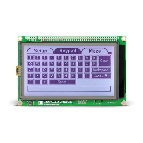
Page 18: Touch Screen
The development system features Graphical LCD 240x128 display covered with a resistive touch panel. Together they form a functional unit called a touch screen. It enables data to be entered and displayed at the same time. The way of entering and displaying data depends on the program loaded into the microcontroller. - Page 19 GLCD-FS BC556 BAT43 BC546 GLCD-D2 GLCD-WR# RIGHT DRIVEA GLCD-D3 GLCD-CE# RA6963 LED-B BC556 GLCD DRIVEA MMC-CD# CONTROLLER mRST# MCLR PIC18F8722 DRIVEB LEFT BC546 OSC2 OSC1 RC5-MOSI RC4-MISO 100nF RC3-SCK BOTTOM LED-R BC546 GLCD-D7 DRIVEB GLCD-D6 GLCD-FS 100nF TOUCH PANEL GLCD-MD 100nF CONTROLLER Figure 5-2-: Touch screen connection schematic...
-
Page 20: Microsd Card Slot
Figure 6-1: microSD card inserted in SmartGLCD There is a built-in microSD card slot for microSD cards provided on the development system. enables the system to additionally expand available memory space. The Serial Peripheral Interface (SPI) is used for Figure 6-2: Inserting... - Page 21 VCC-3.3 VCCA VCCB GLCD-FS 100nF 100nF RC4-MISO 74LVC1T45 BAT43 GLCD-D2 GLCD-WR# GLCD-D3 GLCD-CE# VCC-MMC microSD CARD LED-B DRIVEA MMC-CD# 100nF mRST# MCLR PIC18F8722 DRIVEB OSC2 DAT0 OSC1 RC5-MOSI RC4-MISO RC3-SCK LED-R GLCD-D7 GLCD-D6 GLCD-FS VCC-MMC VCC-3.3 REG1 VOUT FERRITE BEAD MC33269DT-3.3 100nF 100nF...
-
Page 22: Usb Uart
Development system can communicate with USB devices via USB UART module. This FT232RL module comes in form of chip which is interface between serial UART on MCU and USB device. Figure 7-2: mikromedia Figure 7-1: Inserting connected with PC the USB cable via USB cable Page 22... - Page 23 GLCD-FS VCC-3.3 UART-TX OSCO BAT43 100nF DTR# DTR# OSCI GLCD-D2 GLCD-WR# GLCD-D3 GLCD-CE# RTS# TEST VCCIO AGND UART-RX LED-B 100nF CBUS0 DRIVEA MMC-CD# CBUS1 mRST# MCLR PIC18F8722 DRIVEB DSR# OSC2 OSC1 DCD# RESET# 10uF CTS# RC5-MOSI CBUS4 3V3OUT RC4-MISO RC3-SCK CBUS2 USBDM LED-R...
-
Page 24: Pinout
C/SPI C/SPI Digital mikroProg Analog I/O Analog Lines Interrupt Lines SPI Lines I2C Lines UART lines Ground 5V power supply 3.3V power supply output Ground Page 24... -
Page 25: Dimensions
140mm (5.51") 14.3mm (0.52") 134mm (5.28") 2.54mm (0.10") 9.7mm (0.44") 1.6mm (0.06") 30mm (1.18") 12.57mm (0.50") 15.61mm (0.61") Tolerance +/- 0.3mm 128mm (5.04") 7mm (0.28") Page 25... - Page 26 Notes: Page 26...
- Page 27 No part of this manual, including product and software described herein, may be reproduced, stored in a retrieval system, translated or transmitted in any form or by any means, without the prior written permission of MikroElektronika. The manual PDF edition can be printed for private or local use, but not for distribution.
- Page 28 SmartGLCD 240x128 If you want to learn more about our products, please visit our website at www.mikroe.com If you are experiencing some problems with any of our products or just need additional information, please place your ticket at www.mikroe.com/en/support If you have any questions, comments or business proposals, do not hesitate to contact us at office@mikroe.com...
Need help?
Do you have a question about the SmartGLCD and is the answer not in the manual?
Questions and answers