Table of Contents
Advertisement
Quick Links
Download this manual
See also:
User Manual
Advertisement
Table of Contents

Related Manuals for mikroElektronika mikroProg


Summary of Contents for mikroElektronika mikroProg
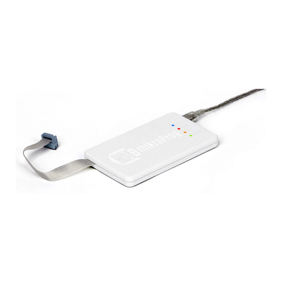
- Page 1 Tiva ™ ™ mikroProg is a fast USB programmer with hardware ™ Debugger support. Smart engineering allows mikroProg ™ to support all Tiva and Stellaris Cortex -M3 and ™ ® ® ™ Cortex -M4 microcontrollers in a single programmer.
- Page 2 TO OUR VALUED CUSTOMERS I want to express my thanks to you for being interested in our products and for having confidence in MikroElektronika. The primary aim of our company is to design and produce high quality electronic products and to constantly improve the performance thereof in order to better suit your needs.
-
Page 3: Table Of Contents
Table of Contents Introduction to mikroProg 6. Connection schematic examples ™ Key features Connecting with LM3SX00 series 1. Driver installation Connecting with LM3S1000 series step 1 – Start installation Connecting with LM3S2000 series step 2 – Accept EULA Connecting with LM3S3000 series step 3 –... -
Page 4: Introduction To Mikroprog
-M4 devices in a single programmer! Outstanding performance, easy operation, elegant design ® ® ™ ™ and low price are it’s top features. It is supported in MikroElektronika ARM compilers, as well as in other ARM compilers. ® ® Page 4... -
Page 5: Key Features
Key features Hardware Debugging - No need for firmware update - New microcontrollers supported via mikroProg Suite latest version of ™ for ARM software ® What you see Flat cable USB MINIB connector DATA transfer indication LED ACTIVE indication LED... -
Page 6: Driver Installation
1. Driver installation On-board mikroProg requires drivers in order to work. Drivers can be found on the link bellow: ™ http://www.mikroe.com/downloads/get/1810/mikroprog_tiva_drivers_v100.zip When you download the drivers, please extract files from the ZIP archive. Folder with extracted files contains folders with drivers for different operating systems. -
Page 7: Step 1 - Start Installation
step 1 – Start installation step 2 – Accept EULA Next> I accept the this EULA In welcome screen click the button In order to proceed select (End User License Agreement) Next> Click the button Page 7... -
Page 8: Step 3 - Installing The Drivers
step 3 – Installing the drivers step 4 – Finish installation Drivers are installed automatically Click the Finish button to end installation process Page 8... -
Page 9: Connecting To A Pc
POWER LED should turn ON, indicating the presence of power supply. Amber-colored LINK LED will turn ON when link between mikroProg and PC is ™ established. Link can be established only when correct drivers are installed on your PC. Page 9... -
Page 10: Mikroprog Suite ™ For Arm ® Software
3. mikroProg Suite for ARM software ™ ® special programming software mikroProg for Tiva programmer requires called mikroProg ™ ™ Suite for ARM . This software is used for programming all Tiva and Stellaris Cortex-M3 ™ ® ™ ® ®... - Page 11 Software installation wizard Start Installation Accept EULA and continue Install for all users Choose destination folder Installation in progress Finish installation Page 11...
-
Page 12: Connecting With A Target Device
IDC10 JTAG connector, as shown on Figure 4-1. In order to make For connection with a target device mikroProg ™ proper connection with the target board it is necessary to pay attention to IDC10 connector pinout. Every pin has a different purpose and for easy orientation IDC10 connector is marked with a little knob and incision between pins number 9 and 7, Figure 5-1. -
Page 13: Connector Pinout
5. Connector Pinout VCC-3.3V - MCU power supply - Ground - Ground - Not Connected - Ground - Mode Select - Clock JTAG programming/ - Data output debugging lines - Data input SRSTn - System Reset Figure 5-1: Female connector pinout Page 13... -
Page 14: Connection Schematic Examples
6. Connection schematic examples Following examples demonstrate connections with some of the most popular supported microcontrollers. Each one is carefully selected as a representative of the entire family. All MCUs use TMS, TCK, TDO, TDI and SRSTn lines for programming. These lines are located on same microcontroller pins within a family. Page 14... -
Page 15: Connecting With Lm3Sx00 Series
VCC-3.3V VCC-3.3V 100K VCC-3.3V SRSTn PC1/TMS ADC0 ADC1 PB3/Fault ADC2 VCC-CORE ADC3 LM3S817 PB1/PWM3 PB0/PWM2 OSC0 PD3/U1Tx OSC1 PD2/U1Rx PC7/CCP4 PD1/PWM1 PD0/PWM0 8MHz 22pF 22pF Figure 6-1: Connection schematics for 48-pin LM3S817 MCU via 2x5 male header Page 15... -
Page 16: Connecting With Lm3S1000 Series
VCC-3.3V VCC-CORE VCC-3.3V 100K VCC-3.3V ADC0 ADC1 SRSTn VDDA PE1/SSI1Fss GNDA PE0/SSI1CLK ADC2 PB3/I2C0SDA ADC3 PB2/I2C0SCL PB1/CCP2 PD0/IDX0 PB0/CCP0 CMOD0 PD2/U1Rx LM3S1538 PD3/U1Tx VDD25 VDD25 PG1/U2Tx PG0/U2Rx VBAT PC7/CCP4 PC6/CCP3 XOSC1 XOSC0 C3 22pF 8MHz C2 22pF Figure 6-2: Connection schematic for 100-pin LM3S1538 MCU via 2x5 male header Page 16... -
Page 17: Connecting With Lm3S2000 Series
VCC-CORE VCC-3.3V VCC-3.3V SRSTn VDDA GNDA PB2/I2C0SCL PB3/I2C0SDA LM3S2B93 VBAT XOSC1 XOSC0 C2 22pF 8MHz C3 22pF Figure 6-3: Connection schematic for 100-pin LM3S2B93 MCU via 2x5 male header Page 17... -
Page 18: Connecting With Lm3S3000 Series
VCC-CORE VCC-3.3V VCC-3.3V PE7/ADC0 PE6/ADC1 SRSTn VDDA USB0RBIAS GNDA PB2/I2C0SCL PE5/ADC2 USB0DP PE4/ADC3 USB0DM PB1/U1Tx PD0/U2Rx PB0/U1Rx PD1/U2Tx PB3/I2C0SDA PD2/CCP6 LM3S3749 PD3/CCP0 VDD25 VDD25 PF1/PWM1 PG3/Fault2 PF2/PWM4 PG2/Fault0 PF3/PWM5 PG1/I2C1SDA PF4/C0o PG0/I2C1SCL VBAT PC7/C1o PC6/PhB0 XOSC1 XOSC0 C2 22pF 8MHz C3 22pF Figure 6-4: Connection schematic for 100-pin LM3S3749 MCU via 2x5 male header Page 18... -
Page 19: Connecting With Lm3S5000 Series
VCC-CORE VCC-3.3V VCC-3.3V SRSTn VDDA USB0RBIAS GNDA PB2/I2C0SCL USB0DP USB0DM PB3/I2C0SDA LM3S5G31 VBAT XOSC1 XOSC0 C2 22pF 8MHz C3 22pF Figure 6-5: Connection schematic for 100-pin LM3S5G31 MCU via 2x5 male header Page 19... -
Page 20: Connecting With Lm3S6000 Series
VCC-3.3V VCC-CORE VCC-3.3V 100K VCC-3.3V ADC0 ADC1 SRSTn VDDA PE1/PWM5 GNDA PE0/PWM4 ADC2 PB3/I2C0SDA ADC3 PB2/I2C0SCL PB1/PWM3 PD0/PWM0 PB0/PWM2 PD1/PWM1 CMOD0 PD2/U1Rx LM3S6537 PD3/U1Tx VDD25 VDD25 XTALPPHY PF2/LED1 XTALNPHY PF3/LED0 MDIO 25MHz VBAT 22pF 22pF PC6/CCP3 XOSC1 XOSC0 C2 22pF 12K4 8MHz C3 22pF... -
Page 21: Connecting With Lm3S8000 Series
VCC-3.3V VCC-CORE VCC-3.3V 100K VCC-3.3V ADC0 ADC1 SRSTn VDDA PE1/PWM5 GNDA PE0/PWM4 ADC2 PB3/I2C0SDA ADC3 PB2/I2C0SCL PB1/PWM3 PD0/CAN0Rx PB0/PWM2 PD1/CAN0Tx CMOD0 PD2/U1Rx LM3S8962 PD3/U1Tx VDD25 VDD25 PF1/IDX1 XTALPPHY PF2/LED1 XTALNPHY PF3/LED0 PG1/PWM1 MDIO 25MHz VBAT 22pF 22pF PC6/PhB0 XOSC1 XOSC0 C2 22pF 12K4 8MHz... -
Page 22: Connecting With Lm3S9000 Series
VCC-CORE VCC-3.3V VCC-3.3V SRSTn VDDA USB0BIAS GNDA PB2/I2C0SCL USB0DP USB0DM PB1/USB0VBUS PB0/USB0ID PB3/I2C0SDA LM3S9B96 XTALPPHY XTALNPHY MDIO 25MHz 22pF 22pF C2 22pF 12K4 8MHz C3 22pF Figure 6-8: Connection schematic for 100-pin LM3S9B96 MCU via 2x5 male header Page 22... -
Page 23: Connecting With Tm4C123 Series
VCC-CORE VCC-3.3V VCC-3.3V SRSTn VDDA VREFA+ VREF- I2C0SDA/PB3 GNDA I2C0SCL/PB2 USB0VBUS/PB1 USB0ID/PB0 OSC1 OSC0 TM4C123GH6PZ 8MHz 22pF 22pF VBAT XOSC1 GNDX XOSC0 Figure 6-9: Connection schematics for 144-pin TM4C123GH6PZ MCU via 2x5 male header Page 23... -
Page 24: Connecting With Tm4C129 Series
VCC-3.3V VCC-3.3V VREFA+ VREF VREFA- VDDC VCC-CORE SRSTn VDDC VDDA VCC-ADC GNDA TM4C129LNCZAD TM4C129LNCZAD TM4C129LNCZAD TM4C129LNCZAD OSC0 VCC-3.3V SRSTn C118 OSC0 22pF C122 C123 C124 C125 C126 C127 C128 C129 C130 C131 C132 C133 GNDX2 GNDX2 WAKE OSC1 25MHz 100nF 100nF 100nF 100nF... - Page 25 Notes:...
- Page 26 Notes: Page 26...
- Page 27 No part of this manual, including product and software described herein, may be reproduced, stored in a retrieval system, translated or transmitted in any form or by any means, without the prior written permission of MikroElektronika. The manual PDF edition can be printed for private or local use, but not for distribution.
- Page 28 If you are experiencing some problems with any of our products or just need additional information, please place your ticket at www.mikroe.com/support/ If you have any questions, comments or business proposals, mikroProg for Tiva Manual ver. 1.00 do not hesitate to contact us at office@mikroe.com...
- Page 29 Mouser Electronics Authorized Distributor Click to View Pricing, Inventory, Delivery & Lifecycle Information: MikroElektronika MIKROE-1505...
Need help?
Do you have a question about the mikroProg and is the answer not in the manual?
Questions and answers