
Related Manuals for Enwork Grid XTB


Summary of Contents for Enwork Grid XTB
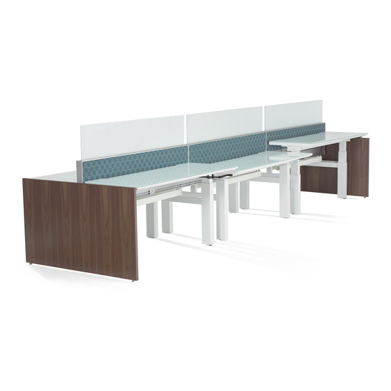
- Page 1 Grid XTB with UMM bases (Shipped after March, 2015) Installation Instructions Rev 0715...
-
Page 2: Tools Needed
Tools Needed 1/4” Drive Socket Wrench 3/8” Box End 13mm Socket Wrench 5mm & 6mm Drill/Driver Tape Measure Allen Wrench #2 Phillips Bit #2 Square Drive... - Page 3 PARTS AND HARDWARE NEEDED FOR STEP 1 M8 – 1.25 X 12MM Button socket head cap screw (qty 8) M6 - 1.0 x 30mm Socket head cap screw (qty 12) Rail Components Socket Bushing (qty 12) Right Hand Column Top Supports Left Hand Column...
- Page 4 STEP 1: ASSEMBLE ALL SINGLE SIDES OF GRID BASES LEFT SIDE OUTER RAIL INSIDE RAIL PRESSURE PLATE M8 – 1.25 X 12MM RIGHT SIDE OUTER RAIL SOCKET BUSHING M6-1.0 X 30MM...
- Page 5 STEP 2: ASSEMBLE LINKS AND RISERS 1/4-28 X 1” Pan Head 1/4-28 Hex Nut 1/4-28 X 3” Pan Head Machine Screw (qty 1) Machine Screw (qty 1 for optional (qty 1) riser) NOTE: 1/4-28 X 1” Pan Head Machine Screw Link Length will be 22”...
- Page 6 STEP 3 TERMINOLOGY End of Run Mid Run End of Run...
- Page 7 Take special notice to link orientation. Slots STEP 3: ASSEMBLE 2-PACK must face towards the outside of the GRID BASES assembly in all mid run conditions, and in all end of run conditions where an end panel will be installed. In end of run conditions where there will be no end panel, the slots must face toward the inside of the assembly.
- Page 8 STEP 4: CONNECT INDIVIDUAL 2-PACKS INTO 4, 6, OR 8-PACKS WORKSTATIONS 1/4-28 X 1” Pan Head Machine Screw (qty 2 per Cross Link) Cross Link (qty 2) 1/4-28 X 1” Pan Head Machine Screw...
- Page 9 STEP 5: CONNECT FRAME TO BASE 10-24 X 2” SOCKET UZWNUTA HEAD CAP SCREW (qty 4 per frame) (qty 4 per frame) Align to center set of holes in frame when attaching 10-24 X 2” SOCKET UZWNUTA HEAD CAP SCREW...
- Page 10 STEP 6: LEVEL AND ALIGN ENTIRE ASSEMBLY ALIGN SPINE LEVEL ALONG SPINE LEVEL ASSEMBLY...
- Page 11 STEP 7: REMOVE FRAME TOP CAP Use #2 square drive bit to remove attachment screws...
- Page 12 STEP 8: CONNECT FRAMES 10-24 X 3/8” PAN 10-24 NYLOCK NUT HEAD SCREW (qty 2) (qty 2)
-
Page 13: Data Connections
STEP 9: POWER AND DATA CONNECTIONS MAKE ALL POWER AND DATA CONNECTIONS, DROPPING THE CABLES IN THE OPENING CREATED BY REMOVING THE FRAME TOP CAP IN STEP 6. EXAMPLES SHOWN IN PICTIRES BELOW. STEP 10: RECONNECT GRID TOP CAP THAT WAS REMOVED IN STEP 6... - Page 14 Channel STEP 11: ATTACH TOPPER SCREENS a) CHECK TO BE SURE CHANNEL IN FRAME IS CLEAR OF DEBRIS b) TRIM GASKET TO LENGTH OF TOPPER SCREEN Topper Screen c) INSTALL GASKET ONTO SCREEN d) WIPE OUTSIDE OF GASKET DOWN WITH SOAPY WATER IN ORDER TO HELP LUBRICATE INSTALLATION Gasket e) USING TWO PEOPLE, CENTER GASKET ON FRAME, AND FIRMLY...
- Page 15 STEP 12: ATTACH WORKSURFACES...
-
Page 16: Step 13: End Panels
STEP 13: END PANELS Threaded Insert M6 - 1.0 x 30mm 1/4-28 X 1” Pan Head Socket Bushing (qty 4 per end panel) Socket head cap screw Machine Screw (qty 4 per end panel) (qty 4 per and panel) (qty 2 per end panel) a) INSTALL THREADED INSERTS INTO END PANEL b) ATTACH BRACKET TO END PANEL M6 - 1.0 x 30mm...
Need help?
Do you have a question about the Grid XTB and is the answer not in the manual?
Questions and answers