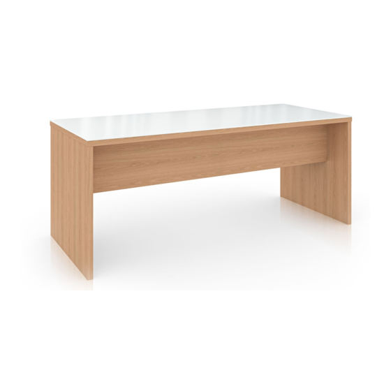
Summary of Contents for Enwork Landing
- Page 1 Landing Landing Team Table (Solid Surface/Quartz) Installation Instruction Installation Instructions Rev A 7/30/18...
- Page 2 INSTALLATION GUIDE 1) Parts and Fasteners Included 8mm x 1in Dowel Pins 24mm Cam Dowel #10 x 2 Phillips Screw Keel Block Keel #10 x 1 Phillips Screw End Panel Sub Top Top Surface...
- Page 3 INSTALLATION GUIDE 1) Parts and Fasteners Included Wire Chase (Left & Right) Angle Bracket Wire Chase Door Panel...
- Page 4 INSTALLATION GUIDE 1) Parts and Fasteners Included Optional Foot Bar Parts Angle Bracket 5/16 Flange Nut #10 x 1 Phillips Screw Foot Bar Weldment...
-
Page 5: Tools And Supplies Required
INSTALLATION GUIDE 2) Tools and Supplies Required Phillips Drive Phillips Head Screw Driver Rubber Mallet 5/16 Deep Socket Cordless Drill Ratchet... - Page 6 INSTALLATION GUIDE Keel Sub Assembly 4) Assembly: Fig. 1 Install (4) Cam Dowels Pins into the (4) centrally located 5mm pre drilled holes on the Keel. Repeat for second Keel. Fig. 1 Fig. 2 Assemble Keel Block and Keels. Keel Blocks should be assembled with the Cam Dowel surfaces facing each other(as shown).
-
Page 7: Base Sub Assembly
INSTALLATION GUIDE Base Sub Assembly 4) Assembly: Fig. 4 Install (4) Cam Dowels Pins & (6) 8mm Dowels Pins into (10) centrally located pre drilled holes on the End Panel. Repeat for second End Panel. Fig. 4 Fig. 5 Align the Cam Dowels and Dowel Pins and assemble the (2) End Panels and the Keel Sub Assembly. -
Page 8: Top Assembly
INSTALLATION GUIDE Top Assembly 4) Assembly: Fig. 7 Insert the 8mm Cam Dowels Pins into the 5mm pre-drilled holes on the Sub Top (bottom surface shown). Fig. 7 Fig 8. Align the Cam Dowels Pins and Cams and assemble the Sub Top to the Base Sub Assembly. Cam the Sub Top and the Base Sub Assembly together. - Page 9 INSTALLATION GUIDE Top Assembly 4) Assembly: Fig. 10 Align the Top Surface with the 8mm Dowel Pins and install the Top Surface. Fig. 10 Fig. 11 Insert Cam Dowels Pins into the 5mm pre- drilled holes on the End Panels. Align the Cam Dowel Pins and Cams and assemble the Wire Chase Side Panels.
- Page 10 Fig. 13 Install the Angel Brackets to the End Panels and Wire Chases using the 1/8in pre drilled holes. Secure using #10 x 1 Phillips Screw Fig. 13 Fig. 14 Install Wire Chase Door Panels Fig.14 Fig. 15 Level the Landing Table using the End Panel Levelers. Fig.15...
- Page 11 INSTALLATION GUIDE Optional Foot Bar Assembly 4) Assembly: Fig. 16 Attach Angle Bracket to End Panel with (4) #10 x 1 Phillips Screws using 1/8in predrilled holes. Repeat for opposite End Panel. Fig. 16 Fig. 17 Attach foot Bar Weldment using (2) 5/16 Flange Nuts.
- Page 12 12900 Christopher Drive Lowell, MI 49331 800.815.7251 www.enwork.com Specifications subject to change without notice.


Need help?
Do you have a question about the Landing and is the answer not in the manual?
Questions and answers