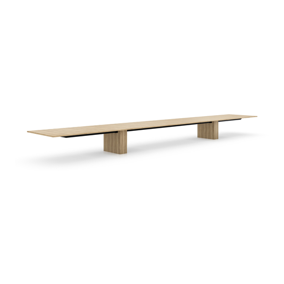
Summary of Contents for Enwork FE Series
- Page 1 Foundation EX Table FExxxx Installation Instructions F A x x x x Foundation EX Installation Guide REV A DATE:(08/01/22)
- Page 2 INSTALLATION GUIDE 1) Parts and Fasteners Included .375-16 x 1.25” .375-16 x 2.25” .25-20 x .50” .50-13 x 4.00” .375-16 Steel Square Nut .375-16 x .50“ Draw Plate 1 Draw Plate 2 #12 x 1.00” Screw (EAM-1000-1) (EAM-2000) F A x x x x Foundation EX Installation Guide REV A DATE:(08/01/22)
- Page 3 INSTALLATION GUIDE 1) Parts and Fasteners Included C-Channel .375 -16 Easy Adjust Glide (EAM-1001-xx) .25”-20 HEX Nut Base Leg 1 Base Bottom Assembly Base Leg 2 (FEM-2006-01) (FEM-2004-x) (FEM-2006-02) Top Plate Assembly Laminate Base Shroud (FEM-2003-x) (FES-1092-x) F A x x x x Foundation EX Installation Guide REV A DATE:(08/01/22)
- Page 4 INSTALLATION GUIDE 1) Parts and Fasteners Included Right Angle Bracket #6-18 x .50” #10-24 X .50” Top Connection Bracket Extrusion Cap Embedded Brace (EAM-1024) (EAM-2010-x) (NZBRACEx) Right Extrusion Mid Extrusion Left Extrusion (EAA-2002-x-R) (EAA-2002-x-M) (EAA-2002-x-L) (EAA-2003-x-R) (EAA-2003-x-L) F A x x x x Foundation EX Installation Guide REV A DATE:(08/01/22)
-
Page 5: Tools And Supplies Required
INSTALLATION GUIDE 2) Tools and supplies Required Drill Hex Driver Bit Square Driver bit Philips Driver Bit Level Philips Screw Driver Combination Wrench Tape Measure Dead Blow Hammer F A x x x x Foundation EX Installation Guide REV A DATE:(08/01/22) - Page 6 INSTALLATION GUIDE 2) Tools and supplies Required Ratchet Socket Utility Knife Marker F A x x x x Foundation EX Installation Guide REV A DATE:(08/01/22)
-
Page 7: Base Assembly
INSTALLATION GUIDE 3) Base Assembly Install the glides into the Base Bottom Assembly. Note: 8X assemblies Fig 3.1 Line up Base Leg 1 with the inside connection holes on the Base Bottom Assembly. Secure together with .375-16 x 1.25” bolts. Note: 2X assemblies Fig 3.2 Line up Base Leg 2 with the outside connection... - Page 8 INSTALLATION GUIDE 3) Base Assembly Carefully pick up and slide the Laminate Shroud down over the Base Legs, until it covers the Bottom Base Assembly. Fig 3.4 Carefully lift up the Top Plate Assembly, align it over the Base Shroud with its connection holes. Slowly let the Top Plate Assembly down until it is resting on the top of the Base legs.
- Page 9 INSTALLATION GUIDE 3) Base Assembly Connect the Right Angle Bracket to the inside of the Base Shroud using a #6-18 x .50” screw provided. Note: 2X assemblies Fig 3.7 Repeat the last seven steps to assemble the second base. When the base assemblies are completed, place them in there final position with the access doors facing in.
- Page 10 INSTALLATION GUIDE 4) Extrusion Assembly In a clear area, on a non marring surface, place the extrusions in an order similar to there completed position. Note: the orientation of the extrusions. (The number of Mid-Extrusions(0-2) is dependent on table length) Fig 4.1 Position the C Channel with the embossed “T”...
- Page 11 INSTALLATION GUIDE 4) Extrusion Assembly Slide the next extrusion on to the C-Channel. Install Draw Plate 1, Draw Plate 2 and a .50 -13 X 4.00” bolt into each Extrusion connection hole and tighten so the extrusions line up flush on all sides. Important: The extrusions must be aligned and square before they fully tightening.
- Page 12 INSTALLATION GUIDE 5) Table Frame Assembly Place the fully assembled beams on the Base Assembly, seating the channel of the extrusion in the U Channel of the base. Note: There may only be (2) beams on each side depending on the size of the table length. Fig 5.1 Align the holes of the assembled beams to the holes of the assembled bases.
- Page 13 INSTALLATION GUIDE 5) Table Frame Assembly Note: if this assembly does not have mid beams, skip ahead to section 6. If this is an assembly with mid beams, position a Left & Right Extrusion as shown. Slide the extrusions completely until the surfaces meet.
- Page 14 INSTALLATION GUIDE 6) Table Top Assembly Insert the .375-16 Square Nuts into the top and bottom track on the inside of the extrusions There will be 2 for every Top Connection Bracket (EAM-1024). Fig 6.1 Attach the Top Connection Bracket to the square nuts using .375-16 x .50”...
- Page 15 INSTALLATION GUIDE 6) Table Top Assembly On a non-marring surface, attach the Embedded Braces to the routings in the bottom of the Top using the #10 x 1.00 Pan Head Phillips Wood Screws. When attaching the braces to the ENDS of the work surface.
- Page 16 INSTALLATION GUIDE 6) Table Top Assembly Verify the work surface is aligned and centered, then fully tighten the Tight Joints. Attach the work surface to the table assembly using the Top Connection Bracket and “12 x 1” screws. Fig 6.7 Fig 6.6 F A x x x x Foundation EX Installation Guide REV A DATE:(08/01/22)
- Page 17 INSTALLATION GUIDE 7) Leveling and Finish Placing a Level in center of the work surface, level the entire table using a ratchet to adjust the glides of each base. Fig 7.1 Feed any power cords down through the base top plate, and down into the floor core (Fig 7.2) (if used) Fig 7.2 Line up and re attach the inside access panel.
- Page 18 12900 Christopher Drive Lowell, MI 49331 800.815.7251 www.enwork.com Specifications subject to change without notice. F A x x x x Foundation EX Installation Guide REV A DATE:(08/01/22)


Need help?
Do you have a question about the FE Series and is the answer not in the manual?
Questions and answers