Advertisement
Quick Links
Advertisement

Related Manuals for Enwork TI0022


Summary of Contents for Enwork TI0022
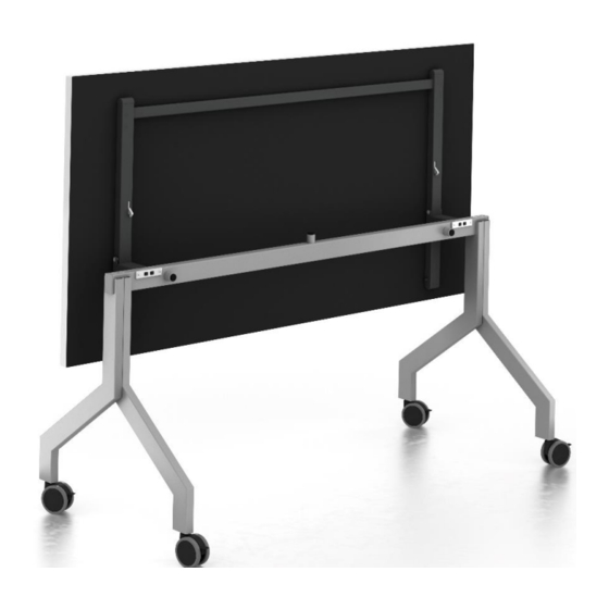
- Page 1 Ritz Flip Table Ritz Flip Table Installation Guide TI0022 Ritz Table Installation Guide – 10/30/17...
- Page 2 INSTALLATION GUIDE 1) Parts and Fasteners Included LEG COLUMN LEG CONNECTION KEY FRAME SUB ASSEMBLY ( RZLEGS) (RZLEGS) (RZNTxxxx) CASTER CASTER PIN M8-1.25 x 70mm (RZCB) (RZCB) PLASTIC END CAP #10 x 1.00” WOOD SCREW WORKSURFACE (RZEC) (CRFxxxx)
- Page 3 INSTALLATION GUIDE 1) Parts and Fasteners Included CAP COVER...
-
Page 4: Tools And Supplies Required
INSTALLATION GUIDE 2) Tools and Supplies Required #2 PHILLIPS BIT DRILL/DRIVER 5mm HEX BIT (#2 SQUARE BIT OPTIONAL) HAMMER (SAND MALLET OPTIONAL) -
Page 5: Assembly Overview
INSTALLATION GUIDE 3) Assembly Overview 1. Leg Assembly 2. Leg Attachment 3. Frame Placement 4. Frame Attachment Figure 3.1 Figure 3.2 Figure 3.3... - Page 6 INSTALLATION GUIDE Leg Assembly 4) Assembly: • Locate the caster and caster pin. • Using a hammer, carefully knock the caster pin into the caster until it is completely seated. Figure 4.1 • Locate one of the leg columns. • Firmly press the caster pin into the bottom of the leg column.
- Page 7 INSTALLATION GUIDE Leg Assembly (continued) 4) Assembly: • Locate the leg connection key. • Insert the key into the slot of the single leg. Figure 4.4 • Insert the second leg component onto the other side of the key. • Slide the second leg up until the tops of the legs are even.
- Page 8 INSTALLATION GUIDE Leg Attachment 4) Assembly: • Locate the pre-assembled frame sub-assembly • Locate the M8 x 70mm Flat head bolts included in the hardware pack. Figure 4.7 • While holding the leg columns together, line up the mounting holes in the legs with the clearance holes in the frame sub assembly.
- Page 9 INSTALLATION GUIDE Frame Placement and Attachment 4) Assembly: Figure 4.10 • Lay the top face down on a non-marring surface. • Place the frame on the top with the black flip mechanisms spaced evenly from the sides of the table. •...
- Page 10 12900 Christopher Drive Lowell, MI 49331 800.815.7251 www.enwork.com Specifications subject to change without notice.
Need help?
Do you have a question about the TI0022 and is the answer not in the manual?
Questions and answers