
Subscribe to Our Youtube Channel
Related Manuals for GEZE Powerturn Series


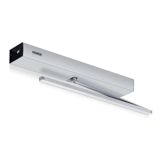
Summary of Contents for GEZE Powerturn Series
- Page 1 Powerturn EN Installation and service instructions Valid for variants: Powerturn (1-leaf/2-leaf) Powerturn F (1-leaf) Powerturn F-IS (2-leaf) Powerturn F/R (1-leaf) Powerturn F/R-IS (2-leaf) 156563-02...
-
Page 2: Table Of Contents
Safety notices ........................................5 Safety-conscious working .....................................6 Inspection of the installed system ................................6 Environmentally conscious working .................................6 Tools and aids ................................6 Supplied by GEZE and completeness .......................7 Transportation and storage ..........................7 Product description ..............................8 System description and technical data ..............................8 5.1.1 Max. - Page 3 Powerturn 7.12 Inserting the counter piece ..................................32 7.13 Installing the spindle extension ................................32 7.14 Installing the shaft cover .................................... 33 7.15 Fitting the mounting aid .................................... 34 7.16 Installing and removing the lever (for installation with roller guide rail) ................. 34 7.16.1 Installing the lever ......................................
-
Page 4: Symbols And Illustrations
Powerturn Symbols and illustrations Warning notices Warning notices are used in these instructions to warn you of property damage and personal injury. Always read and observe these warning notices. Observe all the measures that are marked with the warning symbol and warning word. Warning Warning word Meaning symbol... -
Page 5: Safety Notices
à The country-specific laws and regulations are to be observed during safety-related tests. à If unauthorised changes are made to the system, GEZE cannot be held liable in any way whatsoever for any resulting damage, and the approval for use in emergency exits ceases. -
Page 6: Safety-Conscious Working
Tools and aids Powerturn Safety-conscious working à Secure workplace against unauthorised entry. à Watch swivelling range of long system parts. à Never carry out work with a high safety risk (e.g. installing the drive, cover or door leaf) while alone. à... -
Page 7: Supplied By Geze And Completeness
Powerturn Supplied by GEZE and completeness Supplied by GEZE and completeness Open packaging units and check for completeness. Powerturn door drive with roller guide rail or link arm à Drive unit à Drive à Set of fixing screws à Counter piece, set for fastening the lever à... -
Page 8: Product Description
Product description Powerturn Product description 5. 1 System description and technical data The Powerturn à is a swing door drive with fully automatic operation activated by sensors or push buttons, à operates electrically during opening and closing. It can be used in conjunction with 2-leaf doors (with 2x Powerturn). 5. -
Page 9: Basic Structure And Extension
Powerturn Product description Basic structure and extension 5.2. 1 Drive Side panels Mounting plate Drive axle, continuous Motor gear unit Control Cover Cap section cover E-cover Connector panel 5.2.2 Roller guide rail with lever Installation depends on the type of door stop chosen. Standard roller guide rail with lever: End cap Roller guide rail... -
Page 10: Link Arm
Product description Powerturn 5.2.3 Link arm Standard link arm: Sensor link arm (with link arm adapter): 5.2.4 Activation devices (accessories) Refer to the wiring diagram for the Powerturn. Types of installation, type of door stop à The opening angle of the door always has to be limited by a door stop buffer. à... - Page 11 Powerturn Product description Type of installation Dimension Powerturn Powerturn F Door installation hinge side rail Reveal depth LT [mm] 0–50 Door overlap Ü [mm] 0–30 Max. door opening angle TÖW [°] approx. 126 Standard roller guide rail L = [mm] Lever L = [mm] Hinge size [mm]...
-
Page 12: Preparing Installation
Preparing installation Powerturn Transom installation-opposite hinge side-link arm / jamb / max. door opening angle chart Reveal depth [mm] Door opening angle (TÖW) Door opening angle (TÖW) with sensor link arm Transom installation-hinge side-rail / jamb / max. door opening angle chart Reveal depth [mm] Preload Lever 330 mm... -
Page 13: Preparations To Be Made On-Site
Powerturn Preparing installation 6. 1 . 1 Preparations to be made on-site Checking of the location conditions and the required space à The suspfending frame must ensure safe attachment of the drive. à The bottom edge of the element mounted at the lowest point (roller guide rail or link arm) must be mounted at least 2 m above the floor. -
Page 14: Fitting Dimensions For The Installation Types
Preparing installation Powerturn Fitting dimensions for the installation types 6.2. 1 Transom installation hinge side with standard roller guide rail à Hole pattern DIN left and DIN right reversed. à Follow different installation instructions for a sensor roller guide rail. Fastening DIN left Fastening DIN right Dimensional reference centre of hinge/top edge of door... -
Page 15: Transom Installation Opposite Hinge Side With Standard Roller Guide Rail
Powerturn Preparing installation 6.2.2 Transom installation opposite hinge side with standard roller guide rail à Hole pattern DIN left and DIN right reversed. à Follow different installation instructions for a sensor roller guide rail. Fastening DIN right Fastening DIN left Dimensional reference centre of hinge/bottom edge of frame Concealed line-feed possible in the hatched area, e.g. -
Page 16: Door Leaf Installation, Hinge Side, With Standard Roller Guide Rail
Preparing installation Powerturn 6.2.3 Door leaf installation, hinge side, with standard roller guide rail Hole pattern DIN left and DIN right reversed. Fastening DIN left Fastening DIN right Dimensional reference centre of hinge/top edge of door Directional arrow for precise positioning of the mounting plate Hinge size 220 mm Fasteners Steel/aluminium doors... -
Page 17: Door Leaf Installation, Opposite Hinge Side, With Standard Roller Guide Rail
Powerturn Preparing installation 6.2.4 Door leaf installation, opposite hinge side, with standard roller guide rail Hole pattern DIN left and DIN right reversed. Fastening DIN right Fastening DIN left Dimensional reference centre of hinge/bottom edge of frame Directional arrow for precise positioning of the mounting plate Hinge size 220 mm Fasteners Steel/aluminium doors... -
Page 18: Door Installation, Hinge Side, With Link Arm
Preparing installation Powerturn 6.2.5 Door installation, hinge side, with link arm Hole pattern DIN left and DIN right reversed. Fastening DIN left Fastening DIN right Dimensional reference centre of hinge Directional arrow for precise positioning of the mounting plate Hinge size 220 mm Fasteners Steel/aluminium doors Wooden doors... -
Page 19: Transom Installation Opposite Hinge Side With Link Arm
Powerturn Preparing installation 6.2.6 Transom installation opposite hinge side with link arm Hole pattern DIN left and DIN right reversed. Fastening DIN right Fastening DIN left Dimensional reference centre of hinge Concealed line-feed possible in the hatched area, e.g. Ø 20 mm for the mains connection cable or low-voltage connection Directional arrow for precise positioning of the mounting plate Hinge size 190 mm... -
Page 20: 1-Leaf Installation With Cover Extension Kit Or Extended Cover
Preparing installation Powerturn 6.2.7 1-leaf installation with cover extension kit or extended cover Only install approved components. Divided cover, length = min. 115 mm Install the mounting plate (1) (refer to chapter 7.1). Slide the template (2) into the mounting plate (1). - Page 21 Powerturn Preparing installation Take the side panel (7) off the drive. Push the additional side panel (8) into the side panel from below. Not for continuous cover. Attach the side panel (9) to the cover fixing (5) using 2 screws M5 × 10 (10). Push the divided cover (11) or, as the case may be, the continuous cover, onto the cover fixing.
-
Page 22: 2-Leaf Installation With Intermediate Cover Kit With Divided Or Continuous Cover
Preparing installation Powerturn 6.2.8 2-leaf installation with intermediate cover kit with divided or continuous cover Adjust the position of the base plate (2) in the centre or in relation to the shape of the door, using a spirit level if necessary. If a smoke switch is installed, the V-marking (1) must be pointing towards the active leaf. -
Page 23: Installation
Powerturn Installation Screw down the mounting plate (3). Install the 2nd drive on the right side in the same way. 1 0 7 Installation Heed the installation check list in chapter 11. 7. 1 Installing the mounting plate à Make sure the mounting plate is in the correct position, see directional arrow (1). -
Page 24: Preparing The Electrical Connection
Installation Powerturn Screw the door transmission cable onto the connection bracket (2). Preparing side panel The pocket (4) only needs to be cut out if a door transmission cable is being used. à For all other installation types, carefully detach both side panels (1) and (2). Remove the side panels from the packag- ing and carefully detach the left-hand side panel (2). -
Page 25: Preparing The Drive
Powerturn Installation Preparing the drive With regard to the drive, detach the clamping claw (3) located on the lower side after the drive has been installed. Only loosen the clamping claw by approx. 3–6 mm otherwise the flat ribbon cable could slip out of the clamping claw (3). Danger of crushing the cable. -
Page 26: Hooking The Drive Into The Mounting Plate
Installation Powerturn Hooking the drive into the mounting plate If there is insufficient space above the drive, insert the counterpiece (1) and the optional spindle extension be- fore the drive is installed (see chapter 7.12 and 7.13). Hook the drive (2) into the mounting plate (3) from above. The clamping claw (4) and the section (5) of the mounting plate (3) must line up with each other for this. -
Page 27: Access To The 230-V Connection With Drive Installed
Powerturn Installation The drive is considered to have been installed properly when the screw tunnel (8) for the screw (7) is aligned. Screw in the screw (7) (M6 × 40) (tightening torque ca. 10 Nm). Tighten the screws (6) at the lower clamping claw (tightening torque ca. - Page 28 Installation Powerturn Shift the connector panel (6) in the direction of the flat ribbon cable. Remove the flat ribbon cable from the pocket (7). Use a screwdriver to remove the connector panel casing (8), and detach it in the direc- tion of the arrow.
-
Page 29: Establishing Electrical Plug-In Connections
Powerturn Installation The 230-V terminal (9) is now accessible and can be connected. When the installation process is being carried out in the reverse order, ensure that the flat ribbon cables are laid out properly. Establishing electrical plug-in connections Connect the sensor cables and control cables (1) to the enclosed plug-in connector (2) as per the wiring diagram. -
Page 30: Installing Cable Holders
Installation Powerturn Installing cable holders A cable holder can be used to route further cables through the drive. The max. cable diameter at the top and bottom is 6 mm. For 2-leaf systems there is a danger of collision with the closing sequence control Powerturn IS. Insert the cable holder (1) onto the gear at the top or bottom. -
Page 31: Installing The Integrated Opening Restrictor
Powerturn Installation Screw the standard roller guide rail on with 2 screws. 7. 1 0 Installing the integrated opening restrictor The installation process for the integrated opening restrictor (1) is described in the installation instructions for the opening restrictor (mat. no. 156338). 7. -
Page 32: Inserting The Counter Piece
Installation Powerturn 7. 1 2 Inserting the counter piece If there is insufficient space above the drive, insert the counter piece before the drive is installed. Insert the counter piece (1) into the drive (2) from above. 7. 1 3 Installing the spindle extension Insert the spindle extension (2) into the drive from below. -
Page 33: Installing The Shaft Cover
Powerturn Installation 7. 1 4 Installing the shaft cover Both shaft covers must be inserted before the lever is installed. Preparing the shaft covers Shaft cover on the counter piece side Disconnection points Shaft cover on the lever-side Gate Carefully detach both shaft covers at the disconnection points (2). Dispose of the gate (4). -
Page 34: Fitting The Mounting Aid
Installation Powerturn 7. 1 5 Fitting the mounting aid à The mounting aid (mat. no. 158454) is only required for installing the roller guide rail. It is not required for installing the link arm. à The mounting aid is reusable, and can remain with the fitter. When the mounting aid (2) has been attached, the lever can be tensioned in the direction of the opening in a manner that ensures that it remains in this position. - Page 35 Powerturn Installation Transom installation hinge side with roller guide rail Transom installation opposite hinge side with roller guide rail Note the chart with preload, see “Transom installation-hinge side-rail / jamb / max. door opening angle chart” on page 12 Door leaf installation hinge side with roller guide rail Door leaf installation opposite hinge side with roller guide rail Open the door (1).
-
Page 36: Disassembling The Lever
Installation Powerturn Align the door with the roller guide rail (5) and the suspension bolts (6). Danger of damage to the thread. Ensure that the suspension bolt is screwed in straight. Screw in the suspension bolt (6) and tighten it in a counter-clockwise direction (tightening torque = ca. 15 Nm). Remove the mounting aid. -
Page 37: Installing And Removing The Link Arm
Powerturn Installation 7. 1 7 Installing and removing the link arm 7. 1 7. 1 Installing the link arm 90° 90° 13° Door leaf installation hinge side with link arm Transom installation opposite hinge side with link arm Telescopic rod Lever Screws Door stop buffer... -
Page 38: Installing The Fire Protection Kit
Installation Powerturn 7. 1 8 Installing the fire protection kit à Refer to the wiring diagram (mat. no. 154919) in the chapter dealing with the smoke switch control unit. à For later installation see the supplementary sheet in the fire protection kit (F-Kit). 7. - Page 39 Powerturn Installation Entries on the identification plate (in compliance with DIN 18650-1:2010-06) Reinhold-Vöster-Str. 21-29 DE-71229 Leonberg Powerturn IP30 230V 50Hz Input -15°C/+50°C 200W Output 1,2A Serien-Nr. # MM/JJJJ DIN 18650-1:2010-06 1 3 1 1 2 3 Drive type (first character) Swing door drive (classification factory provided) Durability of the drive (second character) 200,000 test cycles, with at least 1,200 cycles/day...
-
Page 40: Electrical Connection
Electrical connection Powerturn Safety at powered pedestrian doors – version/installation (seventh character) A distinction is made between five classes of safety devices on door leaves: No safety devices With sufficiently dimensioned safety distances With protection against crushing, shearing and drawing-in of fingers with built-in break-out system With sensor-controlled safety devices Note: Several classes may be entered! -
Page 41: Settings
Powerturn Settings Settings 9. 1 Setting the closing force à The closing force must be set at the power storage device for all installation types, so that the door closes in a secure manner (for information regarding the installation types refer to chapter 5.3). à... - Page 42 Settings Powerturn à The illustrations for the EN class setting are only intended as a guide. à The cosing torques to be observed at 0–4° door opening angle are listed in the table below. à Risk of faults on the drive! Do not exceed maximum closing torques. DIN 18263-4 EN 4 EN 5...
-
Page 43: Closing Time And Latching Action Function For De-Energised Operation
Powerturn Settings Closing time and latching action function for de-energised operation Danger of jamming due to excessive door acceleration. Do not set more than 10° latching action on the door. The closing speed must be set using the braking force parameter to match the drive version, type of installation and door weight. -
Page 44: Final Installation
Settings Powerturn Final installation 9.3. 1 Breaking the side panels out Remove side parts (1) and (2) from the packaging, carefully detach them from the bar. Dispose of the gate (3) 1 Right side panel 2 Left side panel 3 Gate 9.3.2 Inserting side panels The side panel can also be inserted after the cover has been put on. - Page 45 Powerturn Settings Clip the side panel in at the front. Inserting the side panel with the e-cover Set the side panel (2) in place at the rear and clip it in. Slide the e-cover (3) over the connector panel.
-
Page 46: Attaching The Cover
Attaching the cover Make sure that no cables become jammed. Clip on the GEZE logo (1) in a suitable position on the cover and turn by 180° if necessary. Slide the cover (2) over the drive and engage it. 9.3.4 Removing the cover and side panels Unlatch the cover and pull it off the drive. -
Page 47: Service And Maintenance
Powerturn Service and maintenance Service and maintenance The maintenance work described below must be performed by an expert at least once a year and after 1 million cycles in the case of the Powerturn or after 500.000 cycles in the case of Powerturn F. If there is a display programme switch, the service display lights up in the display. -
Page 48: Electrical Faults
Powerturn installation check list Powerturn 10.4 Electrical faults Fault messages are stored and can be retrieved using the display programme switch or the service terminal ST220. If a fault is currently active, it is shown every 10 seconds on the display programme switch or the service terminal ST220. If the dot lights up on the left half of the display programme switch, the system was unable to completely initial- ise after being switched on. -
Page 49: Supplementary Installation Sheet For Fitting The Lever In The Correct Position
Powerturn Supplementary installation sheet for fitting the lever in the correct position Test On page In chapter Com- pleted Closing force set? à Set closing force, see supplementary instal- lation sheet, chapter 12 à The closing force for the de-energised state must be set using the braking force parameter. - Page 50 Powerturn installation check list Powerturn...
- Page 52 Powerturn installation check list Powerturn...
- Page 54 Powerturn installation check list Powerturn...
- Page 55 Powerturn Powerturn installation check list...
- Page 56 97944 Boxberg-Schweigern Tel. +49 (0) 7930 9294 0 Baltic States Iberia Singapore Fax +49 (0) 7930 9294 10 GEZE GmbH Baltic States office GEZE Iberia S.R.L. GEZE (Asia Pacific) Pte, Ltd. E-Mail: sk.de@geze.com E-Mail: office-latvia@geze.com E-Mail: info@geze.es E-Mail: gezesea@geze.com.sg www.geze.com...
Need help?
Do you have a question about the Powerturn Series and is the answer not in the manual?
Questions and answers