
Subscribe to Our Youtube Channel
Related Manuals for GEZE Powerturn Series


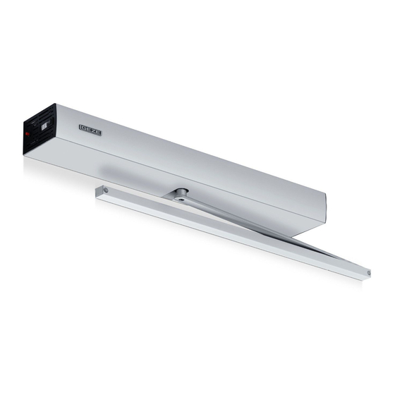
Summary of Contents for GEZE Powerturn Series
- Page 1 Powerturn EN Wiring diagram Valid for variants: Powerturn (1-leaf/2-leaf ) Powerturn F (1-leaf ) Powerturn F-IS (2-leaf ) Powerturn F/R (1-leaf ) Powerturn F/R-IS (2-leaf ) 156568-02...
-
Page 2: Table Of Contents
Powerturn Contents Symbols and illustrations ..............................4 Validity .....................................4 Product liability..................................4 Notes ....................................5 Important safety instructions ..................................5 Installation notes ......................................5 Safe operation ........................................5 Inspection of installed system ..................................5 Disposal of the door system..................................6 Abbreviations................................6 Electrical data................................6 Supply terminals ..............................7 "Open" and "close" safety sensor ........................9 Safety sensor strip pair GC 338 ..................................9 Safety sensor GC 334 .................................... - Page 3 Powerturn Free cable connections ............................31 WC control ................................32 Operation mode ..............................33 16.1 Programme switch ......................................33 16.2 Setting the operation mode using push buttons or switches ....................... 35 16.3 Change in operation mode ..................................36 2-leaf drives ................................37 17.1 Active leaf automated, passive leaf with door closer ........................
-
Page 4: Symbols And Illustrations
Powerturn Symbols and illustrations Warning notices Warning notices are used in these instructions to warn you of property damage and personal injury. Always read and observe these warning notices. Follow all measures that are labelled with the warning symbol and warning word. Warning Warning word Meaning symbol... -
Page 5: Notes
à Unauthorised modifications to the system release GEZE from liability for any resulting damages. à GEZE makes no guarantee in the event of combinations with third-party products. In addition, only original GEZE parts may be used for repair and maintenance work. -
Page 6: Disposal Of The Door System
Abbreviations Powerturn Disposal of the door system à The door system is made up of materials that should be sent for recycling. The individual components have to be sorted in accordance with their material type. à Aluminium (profiles, covers, return pulleys, sliding blocks, ...) à... -
Page 7: Supply Terminals
Powerturn Supply terminals Supply terminals Mains switch DCU800 DCU801 (optional) DCU802 DCU800 RS485 passive leaf FREE DCU801 (optional) 24 V RSZ GND RSZ 24 V RSZ GND second drive... - Page 8 Supply terminals Powerturn DCU802 DPS-RS485 RS485 FREE...
-
Page 9: "Open" And "Close" Safety Sensor
Powerturn "Open" and "close" safety sensor "Open" and "close" safety sensor In the case of 2-leaf systems, connect the safety sensors of the active leaf with the active leaf control and those of the passive leaf with the passive leaf control. Install the sensor for monitoring closing on the door leaf, opposite hinge side. - Page 10 "Open" and "close" safety sensor Powerturn 5.1.1 Monitoring closing and opening Setting the "Contact type" parameter: à DPS: ("NC") (factory set- ting). à ST220: Set the "Input signals", "SI1 – terminal SIS", "SI1 contact type" to "NC" and "SI3 – terminal SIO", "SI3 contact type" to "NC"...
- Page 11 Powerturn "Open" and "close" safety sensor 5.1.2 Monitoring opening Setting the "Contact type" parameter: à DPS: ("NC") (factory setting). à ST220: Set the "Input signals", "SI3 – terminal SIO", "SI3 contact type" to "NC" (factory setting). à S1, S2: Set parameter 9 to 02 (NC). Setting the "Function"...
-
Page 12: Safety Sensor Gc 334
"Open" and "close" safety sensor Powerturn 5.1.3 Monitoring closing Setting the "Contact type" parameter: à DPS: ("NC") (factory setting). à ST220: Set the "Input signals", "SI1 – terminal SIS", "SI1 contact type" to "NC" (factory setting). à S1, S2: Set parameter 7 to 02 (NC). Setting the "Function"... - Page 13 Powerturn "Open" and "close" safety sensor 5.2.1 Monitoring opening GC 334 Setting the "Contact type" parameter: GC 334 module Module à DPS: (NC) (factory setting). 60mA 13 SIO 60mA à ST220: Set the "Input signals", "SI3 – terminal SIO1" and "SI3 contact type" to "NC" 24VSENS (factory setting).
-
Page 14: Safety Sensor Gc 335
"Open" and "close" safety sensor Powerturn 5.2.4 GC 334 connection over interface GC 334 GC 334 module BGS GC 334 Module GC 334 module BS GC 334 Module 60mA 60mA 24VSENS Interface GC 334 GC 334 Door transmission cable Safety sensor GC 335 à... - Page 15 Powerturn "Open" and "close" safety sensor 5.3.1 Monitoring closing and opening Setting the "Contact type" parameter: à DPS: (NC) and (NC) (factory setting). à ST220: Set the "Input signals", "SI1 – terminal SIS1", "SI1 contact type" to "NC" and "SI3 – terminal SIO3", "SI3 contact type" to "NC" (factory setting). Setting the "Function"...
- Page 16 "Open" and "close" safety sensor Powerturn 5.3.2 Monitoring opening Setting the "Contact type" parameter: GC 335 à DPS: (NC) Slaves (factory setting). 60mA 13 SIO à ST220: Set the "Input signals", "SI3 – terminal 60mA SIO1" and "SI3 contact type" to "NC" (factory setting).
-
Page 17: Contact Authorized Sensor
Powerturn Contact authorized sensor Contact authorized sensor à The input KB is active in the AU, LS and NA modes of operation. à In the case of 2-leaf systems, the authorised contact sensor can be connected to the active leaf control or to the passive leaf control. -
Page 18: Gc 302 R Radar Movement Detector
External contact sensor Powerturn GC 302 R radar movement detector à Upon activation, the output of the GC 302 R is closed (24 GC 302 R V applied to the KI input). à Set the Contact type parameter with: 50mA 50 mA 24VSENS à... -
Page 19: Gc 302 R Radar Movement Detector
"normaly open" 23 KA (factory setting). Radio control Observe the installation and service instructions of the GEZE Automatic Wireless Programme, mat. no. 135193. à Radio reception board WRB-5, mat. no. 135170 à 1-channel hand-held radio transmitter, WTH-1, mat. no. 131209... -
Page 20: Insert The Radio Reception Board Wrb-5 To The Control Circuit Board Dcu800
If further radio transmitters are to be taught to channel 1, the steps must be repeated. For further instructions see the GEZE Automatic Wireless Programme installation and service instructions. 9.1.2 Radio channel FK2 The function of the radio channel FK2 is identical to that of actuation input KB. -
Page 21: Push And Go
Powerturn Push And Go Push And Go WARNING Danger of injury due to crushing and shearing! During an activated Push And Go function door handles can form potential danger points. à The Push And Go function allows activation of the drive without contact sensors being used. à... -
Page 22: 2-Leaves. Open And 1-Leaf. Open
Configurable inputs Powerturn 11.2 2-leaves. Open and 1-leaf. Open à The configurable inputs of the active leaf control can be used to change between 2-leaves. Open or 1-leaf. Open as required (depending on the parameter setting). For example, this may be advisable if the opening type is switched by a timer via the available programme switching inputs (NA, LS, AU, DO). -
Page 23: Additional Contact Sensors (P-Ki, P-Ka)
Powerturn Configurable inputs 11.5 Additional contact sensors (P-KI, P-KA) à The configurable inputs can be used to connect additional NO contacts as internal contact sensors or external contact sensors. à Setting the parameters with: à DPS: (internal contact sensor) or to (external contact sensor). -
Page 24: Control Reset
Configurable inputs Powerturn For further settings see the description below. For PE1, PE2, PE3: à Set the Contact type parameter with: à DPS: (normaly open, not monitored) or to (NC, not monitored). à ST220: Set "Signals", "Input signals", "PE1 function", "PE2 function" or "PE3 function" to "Stop opener" or "Stop closer". -
Page 25: Configurable Outputs
Powerturn Configurable outputs Configurable outputs Various switching functions are assigned to configurable outputs PA1 and PA2, see chapter 28 “Service menu”. à To operate the display programme switch DPS see chapter 28.4 “Display programme switch (DPS)”. à To operate the service terminal ST220 see chapter 28.1 “Service terminal ST220”. The state of the drive to which the ST220 is connected is displayed. - Page 26 Configurable outputs Powerturn 12.1.4 Warning signal à The function is used to cyclically switch on/off a customer signal device while the door is opened or closed. à Maximum permissible total current draw of the control. à Setting the parameters with: à...
- Page 27 Powerturn Configurable outputs 12.1.6 Door status message à The function is used to signal the door status, e.g. to a customer building control centre. à Message function/door mode: Closed and locked Night Closed One way Not closed Automatic Open Permanent Open Service due à...
-
Page 28: Configurable Output Pa2
Configurable outputs Powerturn 12.2 Configurable output PA2 PA2 is a transistor output, switching voltage/current max. 24 V DC / 0.5 A. 12.2.1 Gong The output is selected, if KA or SIS (for a "SIS and KA" setting) is activated. à Setting the parameters with: à... - Page 29 Powerturn Configurable outputs 12.2.5 Electric strike à The door opener function is not permissible if the drive is used for the fire protection area (Powerturn F, F/R, F-IS with fire protection kit). à Only inductive DC door openers (without integrated electronics) may be connected to PA2. Door openers with integrated electronics, such as the types effeff 331, 331 U, 331 V, 332, 351 U, etc., have to be connected to configurable output PA1 (see chapter 12.1.5, “Door opener”).
-
Page 30: Door Opener
à Motor lock with panic function GEZE IQ Lock EL for 1-leaf doors. The GEZE IQ Lock EL is a self-locking anti-panic motor lock with external control. See wiring diagram for motor lock IQ Lock EL. IQ Lock SecuLogic set (Motor lock PZ-bored, complete, incl. -
Page 31: Free Cable Connections
Powerturn Free cable connections Customer-supplied 12 V AC door opener Contact load output PA1 at 12 V AC: max. 1 A 12 AC ~ 12V AC ~ max. 1A max. 1A TOEA TOEB Bolt signal à Input RM blocks the activation of the drive when the door is locked. If Input RM becomes active while the door is open, the door reverses and remains open. -
Page 32: Wc Control
WC control Powerturn WC control Only operates with static current door opener. For connection and configuration, see chapter 13 “Door opener”. oder PE1, PE2 PE1, PE2 oder oder PA1 PA2 PA1 PA2 PA1A PA1A PA1B PA1B Internal push button (switch unit with illuminated display) Illuminated OCCUPIED display External push button (switch unit with illuminated display) Signal horn SLH220 (optional) -
Page 33: Operation Mode
Powerturn Operation mode Accessories: à Plastic elbow switch, white, mat. no. 114078 à Plastic elbow switch, stainless steel, mat. no. 114077 à Stainless steel elbow switch, mat. no. 119898 à Stainless steel elbow switch LS 990, surface-mounted, mat. no. 128582 à... - Page 34 Operation mode Powerturn Mechanical programme switch (MPS-D) à MPS-D, AS500, mat. no. 118417 à MPS-D-ST, with key, AS500, mat. no. 118418 à Accessories: Surface-mounted cap, single, AS500, mat. no. 120503 à For 2-leaf systems, the MPS-D is connected to the active leaf.
-
Page 35: Setting The Operation Mode Using Push Buttons Or Switches
Powerturn Operation mode Blocking or releasing DPS operation à Blocking operation by key switch Operation of the DPS can be blocked/released by connecting a key switch to prevent the operation mode being changed by unauthorised persons. Operation is possible using the key switch. à... -
Page 36: Change In Operation Mode
Operation mode Powerturn 16.3 Change in operation mode 16.3.1 Changing the operation mode using the modes of operation push button/modes of operation display Changing the operation mode (with single-leaf doors or active leaves) Press the modes of operation key (1) briefly. The modes of operation display immediately switches one operation mode further. -
Page 37: 17 2-Leaf Drives
Powerturn 2-leaf drives 16.3.2 Changing the operation mode using the service LEDs The service LEDs are used à to indicate system messages, à to indicate and change drive parameters, à to start the production test. During normal operation the LEDs indicate the current operation mode. The operation mode can be changed using keys S1 and S2. -
Page 38: Connection Via System Cable Rs485
2-leaf drives Powerturn 17.3 Connection via system cable RS485 Active leaf Passive leaf System cable RS485 Control circuit board DCU800 17.4 Mains connection Mains cable H03VV 3G 0.75 mm (e.g. mat. no. 158184) For mains plugs, install the rubber grommets, see chapter 19.1, “Mounting plate with integrated feeder”. The mains plugs have spring-type terminals which means connection without wire-end ferrules is permitted. -
Page 39: Smoke Switch Control Unit
Powerturn Smoke switch control unit Smoke switch control unit The required fire protection kit (mat. no. 154876) for Powerturn includes: à F-board DCU801 with fastening screws and spacer à Reset button Installing the F-board DCU801 A jumper must be inserted for controls without an F-board. Remove the jumper (1) if necessary. - Page 40 Smoke switch control unit Powerturn Installing the reset button Break out the position for the reset button on the side part. Insert the reset push button (1) through the side part. Push the retaining ring (2) in place. Connect the power supply cable (3) from the reset push button to the connection (4).
-
Page 41: Integrated Smoke Switch Powerturn F/R
18.1 Integrated smoke switch Powerturn F/R For reasons of appearance the GEZE lintel smoke switch can be integrated in the extension kit or the intermedi- ate cover kit. The extension kit or the intermediate cover kit is supplied with a fixture for this purpose. The smoke switch is inserted into it and the electrical connection is established. -
Page 42: Powerturn F- Is/Ts, F/R-Is/Ts Hold-Open System - Automatic Active Leaf, Passive Leaf With Door Closer And Hold-Open Magnet
à Accessories: à Reed switch, mat. no. 92777 à GEZE magnetic door clamp, mat. no. 115829, 115830, 155569, 155567, 155573, 115952, 115953 à Swing door system IS/TS, mat. no. 160700 à Setting the parameters with: à DPS:... - Page 43 Powerturn Smoke switch control unit 18.2.2 Powerturn F/R-IS/TS DCU802 PA1A PA1B 63mA 63mA DCU801 +24V RSZGND RSZ 24V RSZGND 10mA 10mA Alarm Alarm Powerturn F/R- active leaf Fixed leaf with door closer Reed switch for the pas- +24V sive leaf closed position 15mA 15mA Hold-open magnet...
-
Page 44: Mains Connection
Mains connection Powerturn Mains connection Transom installation 230V 230V 50Hz 50Hz GN/YE Mains fuse Main switch, internal Main switch (optional) to second drive control AC IN Mounting plate Transformer Door leaf installation 230V 230V 50Hz 50Hz GN/YE Mains fuse Transformer Main switch (optional) Main switch, internal Junction box... -
Page 45: Mounting Plate With Integrated Feeder
Powerturn Mains connection 19.1 Mounting plate with integrated feeder 19.1.1 Setup à Make sure the mounting plate is in the correct position, see directional arrow (1). à Mains connection always on the hinge side. à The connection to the drive is on the facing side. - Page 46 Mains connection Powerturn 19.1.3 Connecting to the mains If the mains supply line is connected to the installed drive, the connection board DCU802 must be removed. See Powerturn installation instructions. 9 mm Strip the mains (1). 9 mm à Stripping length = 40 mm à...
-
Page 47: Motor
Powerturn Motor à In the connected state, the rubber grommet (4) must completely enclose the connector (3) and cable (1). à No individual wires may be visible. Motor WARNING Danger of injury through link arm or lever arm snapping back! Disconnect motor from the control only if spring is relaxed. -
Page 48: Control
Control Powerturn Control Slot for F-board DCU801 LED solenoid valve Service buttons and service LEDs PROG LED 24V ext Slot for radio board WRB-5 Brake FREE Ventilator 24 V Encoder RS485 Motor Safety fuse F1, AC IN (10 A T, 5 × 10 mm) Temperature sensor Mains switch Latching action switch... -
Page 49: Commissioning And Service
Powerturn Commissioning and service Commissioning and service Commissioning and service can be performed using the display programme switch DPS, the service terminal ST220 or the internal service keys. 22.1 Commissioning 22.1.1 Requirements à Drive à attached à not taught à set to factory setting * à... -
Page 50: Teaching A 1-Leaf System
Commissioning and service Powerturn 22.3 Teaching a 1-leaf system Step Actions ST220 display DPS display Service LED display (5 Select parameter “Start learning” and press the ENTER Start learning key. Select 1-leaf system. Start the respective teaching in DPS (NT) à... -
Page 51: Teaching A 2-Leaf System
Powerturn Commissioning and service 22.4 Teaching a 2-leaf system Teaching a 2-leaf system with service keys is not possible. Step Actions ST220 display Service LED display display (5 Select parameter “Start learning” and press the ENTER key. Start learning Select 2-leaf system. -
Page 52: Forces And Speeds
Disconnected mode Powerturn 22.5 Forces and speeds 22.5.1 Forces The forces set using "Opening force" (FO), "Per opening pressure" (0F), "Per closing pressure" (CF), "Force closed position" (FS) or "Closing force" (FC) always refer to N at the main closing edge. à... -
Page 53: Resilience To External Influences Or Load Due To Wind Pressure
Powerturn Resilience to external influences or load due to wind pressure Resilience to external influences or load due to wind pressure In the event of exposed exterior doors with high load due to wind pressure or doors exposed to overpressure, the drive can be set using the "Opening force, FO", "Closing force, FC"... -
Page 54: Low-Energy Mode
Low-energy mode Powerturn Low-energy mode à Doors set to low-energy mode generally do not require any additional protective devices, if no particularly vulnerable persons are expected to use the door. à In the case of 2-leaf doors, both drives must have been set to low-energy mode. The Powerturn drive can be operated as a low-energy drive if the following conditions are met: à... -
Page 55: Service Menu
Powerturn Service menu Service menu 28.1 Service terminal ST220 à Service terminal ST220, mat. no. 087261 à Commissioning of the drive is possible with the service terminal ST220, software version V2.1 or higher. à Connection either via 5-pin plug connector RS485 or using a 3.5 mm TRS connector (with adapter cable mat. no. -
Page 56: Connecting Service Terminal St220
Service menu Powerturn 28.2 Connecting service terminal ST220 Service terminal ST220 is connected to connection board DU802 (3) using the bushing for the 3.5 mm TRS con- nector (1) or alternatively at the connector plug for DPS (2). 28.3 Service menu ST220 See chapter 28.6 “DPS service menu and service buttons S1/S2 with LEDs”... - Page 57 Powerturn Service menu 28.3.3 Operation mode Designation Setting values Description Operation mode setting Operation mode Night shop closing Automatic Permanent Open Only open active leaf Type Opening 1. Leaf open Open active and passive leaves 2. Leave Open when actuated Control the door using ST220.
- Page 58 KB in the event of NA, as well as closing the door when switching from DO to AU, requires a few seconds, as the system first has to boot up. Currently not in use. GEZE-bus address Value: value value value 28.3.5 Motion parameters Designation 1.
- Page 59 Powerturn Service menu Designation 1. Sub-menu 2. Sub-menu Description Close static force at the main Closing force Value: 150 N closing edge. 10 N 250 N Time for which the drive pushes Obstacle Value: 3 s *0.1 against an obstacle with the set 1 s *0.1 static force.
- Page 60 Service menu Powerturn Designation 1. Sub-menu 2. Sub-menu Description Automatic extension of the dynamic increase hold-open time at increased usage frequency Reversing in the event of an Reversing Rev. manual Close not active obstacle within closing follow- active ing manual opening. Reversing in the event of an Rev.
- Page 61 Powerturn Service menu 28.3.6 Signals Designation 1. Sub-menu 2. Sub-menu 3. Sub-menu Description Input sig- SI1 - Terminal Current state SI1 - termin l SIS nals Z-> not active K-> normaly closed F->SIS rev SI1 contact unused normaly closed If the safety sensor "close" trig- SI1 function SIS rev gers, the door reverses.
- Page 62 Service menu Powerturn Designation 1. Sub-menu 2. Sub-menu 3. Sub-menu Description Current state Z-> not active K-> normaly open A->0 s KI contact unused normaly closed normaly open Only active when the door is in a KI delay Value: 0 s *0.1 closed position.
- Page 63 Powerturn Service menu Designation 1. Sub-menu 2. Sub-menu 3. Sub-menu Description NC Permanently switched. If the Sabotage contact is interrupted KB is not evaluated in the operation mode "night-time". All other functions remain the same. NO Feedback from the door closer Closed Pos in the closing position (active leaf ).
- Page 64 Service menu Powerturn Designation 1. Sub-menu 2. Sub-menu 3. Sub-menu Description On activation, the output of Pushbutton OHZ NO the push button is closed. With 2-leaf assemblies the push button can be connected to the moving leaf control or to the passive leaf control.
- Page 65 Powerturn Service menu Designation 1. Sub-menu 2. Sub-menu 3. Sub-menu Description 1× press = 1-leaf. Open. Double push 2× press = 2-leaves. Open. NO For connection of a stop push Stop closer button NC For connection of a stop push Stop opener button NO Feedback from the door closer...
- Page 66 Service menu Powerturn Designation 1. Sub-menu 2. Sub-menu 3. Sub-menu Description Output Current state signals Z-> not active K-> normaly open F->unused PA1 function unused If KA is triggered Gong The function is used for fault Error NO messages, e.g. to a customer Error NC building control centre.
- Page 67 Powerturn Service menu Designation 1. Sub-menu 2. Sub-menu 3. Sub-menu Description If KA is triggered Gong see PA1 Error NO Error NC see PA1 Error MPS The function is used to cyclically Warningsignal switch a signal transmitter on/ off while the door is opening or closing.
- Page 68 Service menu Powerturn 28.3.7 Diagnostics Designation 1. Sub-menu 2. Sub-menu Description current values inputs 0,0 V 0,0 V Latching act outputs Open 24 V TEST 24 V 24 V internal data current Position Act. Motor current Mot DCU800 3.24 A Voltages Power 24 V Intern...
- Page 69 Powerturn Service menu Designation 1. Sub-menu 2. Sub-menu Description current conditions inputs Latching act outputs TEST error memory current errors Fault 1 Cause 1 Cause 2 Fault 2 Cause 1 Cause 2 Fault 3 Cause 1 Cause 2 Fault 4 Cause 1 Cause 2 old errors...
- Page 70 Service menu Powerturn 28.3.8 Default values Designation 1. Sub-menu 2. Sub-menu Description All the values are set to standard Default Values setting. Position and open- ing angle are retained. Error memory is deleted. A teaching run and initialisation run are not necessary.
- Page 71 à If the password has been forgotten, a special flash file with which the password on the control can be reset to 00 has to be requested from GEZE. à The password cannot be deleted by installing a new software version 28.3.14 Sprache / Language...
-
Page 72: Display Programme Switch (Dps)
Service menu Powerturn 28.4 Display programme switch (DPS) The DPS can be used for commissioning and servicing, mat. no. 151524: à for changing the drive parameters à for "teaching" the drive à for diagnosis Operation mode Service mode Night × Cancel and return to first menu level One way... - Page 73 Powerturn Service menu System messages à If one or more faults are pending, these are displayed consecutively alternatively with the current operation mode in encoded form with service LEDs 1 to 4. à The red LED5 flashes quickly (10 Hz) on the fault display. à...
-
Page 74: Dps Service Menu And Service Buttons S1/S2 With Leds
Service menu Powerturn 28.6 DPS service menu and service buttons S1/S2 with LEDs à Changing to the service mode is possible in the NA, LS, AU and DO modes of operation. à If no key is pressed in service mode for a period of 2 minutes, an automatic change to the operation mode takes place. - Page 75 Powerturn Service menu DPS Service LEDs Parameter Setting values Description ● ● ○ ○ Door opener type no door opener Working Power door Drive does not have closing force (pressure in opener the closing position) before opening. Quiet current – door opener Motor lock Working Power pressure Drive has closing force (pressure in the clos-...
- Page 76 Service menu Powerturn DPS Service LEDs Parameter Setting values Description – – – – – Hold-open time in s; manual 01 … 10 Hold-open time for manual opening; 12 … 20 Values corresponding to the time. 24 … 50 No automatic closing. – – – – –...
- Page 77 Powerturn Service menu DPS Service LEDs Parameter Setting values Description ** ○ ● ○ ○ Safety closing contact unused (DPS 3rd manu, SI) type (terminal SIS) ** ○ ● ○ ● Safety opening con- unused (DPS 3rd menu, S3) tact type (terminal SIO) 1 flashing pulse + 0.9 s pause...
- Page 78 Service menu Powerturn DPS Service LEDs Parameter Setting values Description ** ○ ● ○ ○ Safety 1 contact type unused Parameter sets the use of the safety sensor (terminal SIS 1) "close" contact type. ** ○ ● ○ ● Safety 3 contact type unused Parameter sets the use of the safety sensor (terminal SIO 1)
- Page 79 Powerturn Service menu DPS Service LEDs Parameter Setting values Description P-KI activation NO Additional contact sensors (P-KI, P-KA) For connection of additional closing con- P-KA activation tacts Pushbutton NO On activation, the output of the push button is closed. With 2-leaf assemblies the push button can be connected to the moving leaf control or to the passive leaf control.
- Page 80 Service menu Powerturn DPS Service LEDs Parameter Setting values Description Sabotage NC Permanently switched. If the contact is in- terrupted KB is not evaluated in the opera- tion mode "night-time". All other functions remain the same. Closing position Feedback from the door closer in the clos- Door closer ing position (active leaf ).
- Page 81 Powerturn Service menu DPS Service LEDs Parameter Setting values Description Closed and locked The function is used to signal the door mode, e.g. to a building control centre. Closed Not closed Open Night One way Automatic Permanent Open Light activation The function is used to actuate a light con- trolling device which, for example, switches on the entry illumination as soon as a...
- Page 82 Service menu Powerturn DPS Service LEDs Parameter Setting values Description – – – – not active – Reversing manual Reversing in the event of an obstacle within closing closing following manual opening: not active active Reversing in the event of an obstacle within closing following manual opening: active –...
-
Page 83: Fault Messages
Powerturn Fault messages Fault messages 29.1 Fault messages ST220 and DPS 29.1.1 Fault display On the DPS à For troubleshooting and fault description see also list "Faults and actions - control DCU2" list. à Currently queued fault messages are displayed on the display programme switch in cycles (10 s). In addition, they are also entered in the error memories. - Page 84 Fault messages Powerturn Error NO. Message Message on the ST220 Fault description on the Rotate angle A cam skip has been detected. Defective magnetic valve The solenoid valve of the energy store is defective. Mechanical fault SF A mechanical fault has occurred at the passive leaf; collective fault. Move angle A cam skip has been detected.
- Page 85 Powerturn Fault messages Error NO. Message Message on the ST220 Fault description on the EEPROM comparison – Current measurement error Error in motor current measurement. EEPROM time-out – Quartz tolerance – RAM test – ROM CRC test – VCC test –...
-
Page 86: Fault Messages On The Service Button Leds
Fault messages Powerturn 29.2 Fault messages on the service button LEDs à Fault messages of fault groups are displayed on the service button LEDs. The exact fault can be determined using the fault number in chapter 29.1.2. à For the service button LEDs, LED 5 flashes at 10 Hz. à... - Page 87 Powerturn Fault messages...
- Page 88 E-Mail: danmark.se@geze.com Tel. +49 (0) 7152 203 594 www.geze.at www.geze.hu www.geze.dk E-Mail: leonberg.de@geze.com Baltic States Iberia Singapore GEZE GmbH Baltic States office GEZE Iberia S.R.L. GEZE (Asia Pacific) Pte, Ltd. GEZE GmbH E-Mail: office-latvia@geze.com E-Mail: info@geze.es E-Mail: gezesea@geze.com.sg Niederlassung Süd-Ost www.geze.com www.geze.es...
Need help?
Do you have a question about the Powerturn Series and is the answer not in the manual?
Questions and answers