Deif GPC-3 Quick Start Manual
Generator paralleling controller/generator protection unit/paralleling and protection unit
Hide thumbs
Also See for GPC-3:
- Designers reference handbook (122 pages) ,
- Installation instructions manual (64 pages) ,
- Operator's manual (29 pages)
Table of Contents
Advertisement
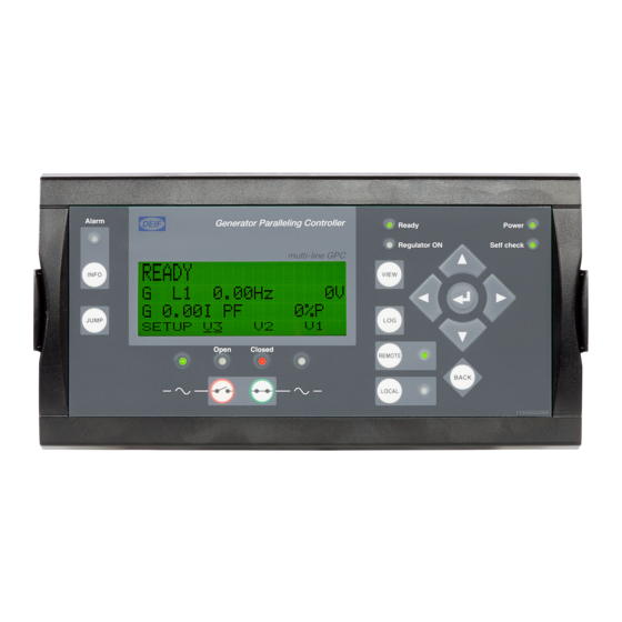
Generator Paralleling Controller, GPC-3
Generator Protection Unit, GPU-3/GPU-3 Hydro
Paralleling and Protection Unit, PPU-3
DEIF A/S · Frisenborgvej 33 · DK-7800 Skive · Tel.: +45 9614 9614 · Fax: +45 9614 9615 · info@deif.com · www.deif.com
QUICK START GUIDE
● What's in the delivery?
● Getting started
● The first steps
● PC utility software
Document no.: 4189340603B
SW version: 3.0X.X or later
Advertisement
Table of Contents

Subscribe to Our Youtube Channel
Related Manuals for Deif GPC-3


Summary of Contents for Deif GPC-3
- Page 1 ● PC utility software DEIF A/S · Frisenborgvej 33 · DK-7800 Skive · Tel.: +45 9614 9614 · Fax: +45 9614 9615 · info@deif.com · www.deif.com isenborgvej 33 · DK-7800 Skive · Tel.: +45 9614 9614 · Fax: +45 9614 9615 · info@deif.com · www.deif.com Document no.: 4189340603B...
-
Page 2: Table Of Contents
3.2.1. Basic wiring for GPU-3 and GPU-3 Hydro...................11 3.2.2. Basic wiring for GPC-3 and PPU-3....................13 4. The first steps 4.1. Basic AC values...........................15 4.2. Getting started with the DEIF utility software (USW)................17 4.2.1. Downloading the software......................17 4.2.2. Installation of USB drivers......................17 4.2.3. Getting connected........................18 4.2.4. -
Page 3: General Information
1.1.2 Legal information and disclaimer DEIF takes no responsibility for installation or operation of the generator set. If there is any doubt about how to install or operate the engine/generator controlled by the Multi-line 2 unit, the company responsible for the installation or the operation of the set must be contacted. -
Page 4: About The Quick Start Guide
1.2.3 Contents and overall structure This document is divided into chapters, and in order to make the structure simple and easy to use, each chapter will begin from the top of a new page. DEIF A/S Page 4 of 23... -
Page 5: What's In The Delivery
ML-2 quick start guide 4189340603 UK What's in the delivery? 2. What's in the delivery? 2.1 Standard delivery The main unit Standard display unit, DU-2 Layout is option-dependent Display cable, 3 m Installation instructions DEIF A/S Page 5 of 23... -
Page 6: Optional Delivery
Display cable with plugs, 6 m (option J2) PC cable for option N programming - Ethernet cable crossed (option J4) Display cable with plugs, 1 m (option J6) PC cable for utility software (option J7) DEIF A/S Page 6 of 23... - Page 7 DC/DC converter and 2 × CAN bus cable 3 m Additional operator panel, AOP-1 (option X3) AOP-1 0.5 m cable Additional operator panel, AOP-2 (option X4) AOP-2 DC/DC converter and 2 × CAN bus cable 3 m DEIF A/S Page 7 of 23...
-
Page 8: Getting Started
3.1.1 Connecting the display with the main unit Connect the SUB-D display cable to the main unit and the display unit as shown in the picture below. No use of tools or brute force when tightening finger-screws on display cable. DEIF A/S Page 8 of 23... -
Page 9: Connecting The Power Supply To The Main Unit
2. Terminal 2: 0 V 3. Option M4 - terminal 98: +24 V 4. Option M4 - terminal 99: 0 V 3.1.3 Connecting the additional operator panel, AOP-1 (optional) Display unit DU-2 AOP-1 cable 0.5 m AOP-1 DEIF A/S Page 9 of 23... -
Page 10: Connecting The Additional Operator Panel, Aop-2 (Optional)
For further information about the installation of multiple displays and AOP-2s, please refer to the document "Description of Option X". DEIF A/S Page 10 of 23... -
Page 11: Wiring
59 60 61 62 63 65 66 69 70 Service port Display Power Self check ok Alarm inhibit 83 84 85 86 96 97 U L3 U L2 U L1 U L1 U L2 U L3 DEIF A/S Page 11 of 23... - Page 12 DC Main + 24 VDC supply 53 54 56 57 59 60 61 62 63 65 66 69 70 Service port Display Power Self check ok Alarm inhibit 83 84 85 86 96 97 DEIF A/S Page 12 of 23...
-
Page 13: Basic Wiring For Gpc-3 And Ppu-3
ML-2 quick start guide 4189340603 UK Getting started 3.2.2 Basic wiring for GPC-3 and PPU-3 AC wiring 53 54 56 57 59 60 61 62 63 65 66 69 70 Service port Display Power Self check ok Alarm inhibit 83 84... - Page 14 37 – P load sharing 53 54 56 57 59 60 61 62 63 65 66 69 70 Service port Display Power Self check ok Alarm inhibit 83 84 85 86 96 97 Down Speed governor DEIF A/S Page 14 of 23...
-
Page 15: The First Steps
This chapter guides you through the most essential parameters which have to be adjusted before you can start using the unit. The set points can either be adjusted from the display unit or by using the DEIF utility software. The following examples will show how to adjust the parameters from the display unit. - Page 16 25000 V range in "9030 Scaling". 6005 Nom. set- 100 RPM 1500 tings 1 4000 RPM 6006 Nom. set- tings 1 To adjust the transformer settings, use the push-button to get to the transformer page. DEIF A/S Page 16 of 23...
-
Page 17: Getting Started With The Deif Utility Software (Usw)
On Windows Vista machines, the USB drivers are installed automatically. This is the procedure on Windows XP machines: When you connect the DEIF product, Windows XP will launch two "Hardware Wizards". Two drivers are in- stalled, so please let Windows execute both "Found new Hardware Wizard"s. -
Page 18: Getting Connected
Connect the service port to the USB on the computer (option J7 or option J3). Click the Utility Software 3 icon on the desktop or in the Windows Start menu. Desktop icon: Quick launch and Start menu icon: The below window appears. DEIF A/S Page 18 of 23... - Page 19 Open "Windows device man- ager". Check the COM port used for communication, and make sure the settings correspond to the application settings. Click the "Connect" icon. You are now online with the unit. DEIF A/S Page 19 of 23...
-
Page 20: Read Parameters From The Device
4.2.5 Basic configuration of a device using the utility software When the parameters have been uploaded, the options below will be available. Click the "Gen" tab. The parameters can be configured as follows: Click a parameter and the dialogue box below will appear. DEIF A/S Page 20 of 23... - Page 21 Click this or use the bar to adjust the setpoint, then click "Write" and "OK". The parameter setpoint has now been changed and downloaded to the device. For further information, please refer to the General Guidelines for Commissioning. DEIF A/S Page 21 of 23...
-
Page 22: Configuring The Speed Governor And Avr Outputs
Option- dep. 2780 Regulator output 2781 Reg. Relay Relay Designer’s Selection of the speed output Reference output: Relay, analogue Handbook or engine interface com- munication. Analogue GPU: and EIC are option-de- Option G2 pendent. DEIF A/S Page 22 of 23... - Page 23 Analogue outputs require option E1, E2, EF2, EF4 or EF5. For further information, please refer to the document "General Guidelines for Commissioning". For further information, please check the following documents: GPC-3 Designer’s Reference Handbook Document no. 4189340587 GPU-3 Designer’s Reference Handbook Document no.
Need help?
Do you have a question about the GPC-3 and is the answer not in the manual?
Questions and answers