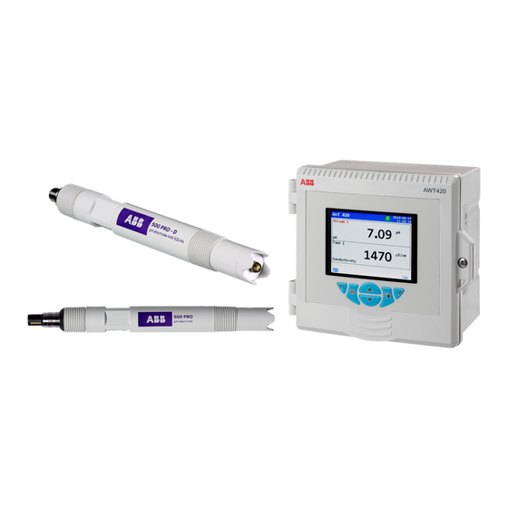
ABB AWT420 Operating Instruction
Universal 4-wire, dual-input transmitter
Hide thumbs
Also See for AWT420:
- Commissioning instructions (40 pages) ,
- Manual (16 pages) ,
- Manual (16 pages)
Table of Contents
Advertisement
Quick Links
—
A B B M E A S U R E M E N T & A N A LY T I C S | O P E R AT I N G I N S T R U C T I O N
AWT420
Universal 4-wire, dual-input transmitter
Introduction
—
AWT420
Universal 4-wire,
The AWT420 is a universal 4-wire, dual-input
dual-input transmitter
transmitter suitable for the measurement and
control of a wide range of parameters including
pH, ORP, conductivity, turbidity/suspended
solids and dissolved oxygen.
The AWT420 supports both traditional analog and
advanced digital EZLink sensors.
This Operating Instruction provides installation,
operation and maintenance procedures for the
AWT420 transmitter. For information on the
sensors, including installation, commissioning,
operation and maintenance procedures, refer to
the specific sensor manual.
Measurement made easy
For more information
Further publications for the AWT420 transmitter
are available for free download from:
www.abb.com/measurement
or by scanning this code:
Links and reference numbers for the transmitter
publications are also shown below:
AWT420 transmitter – Data Sheet
AWT420 transmitter –
Commissioning Instruction
AWT420 transmitter –
HART Communications Supplement
AWT420 transmitter –
HART FDS Communications Supplement
AWT420 transmitter –
PROFIBUS Communications Supplement
AWT420 transmitter –
MODBUS Communications Supplement
AWT420 transmitter –
Ethernet Communications Supplement
Search for/click on:
DS/AWT420-EN
CI/AWT420-EN
COM/AWT420/
HART-EN
COM/AWT420/
HART/FDS-EN
COM/AWT420/
PROFIBUS-EN
COM/AWT420/
MODBUS-EN
COM/AWT420/
ETHERNET-EN
Advertisement
Table of Contents

Related Manuals for ABB AWT420


Summary of Contents for ABB AWT420
-
Page 1: For More Information
Introduction For more information — AWT420 Universal 4-wire, The AWT420 is a universal 4-wire, dual-input Further publications for the AWT420 transmitter dual-input transmitter transmitter suitable for the measurement and are available for free download from: control of a wide range of parameters including www.abb.com/measurement... -
Page 2: Table Of Contents
Sensor addition ........22 AWT420 transmitter – electrical ....5 Sensor replacement . - Page 3 Diagnostic messages ......83 AWT420 transmitter diagnostics ... . . 83 Sensor setup .
- Page 4 Appendix B 2-electrode AWT420 pH PCB upgrade/spares kit ..108 conductivity calculations . . . . . . . . . . . . . . . . . . . . . . . 98 AWT420 2-electrode conductivity PCB upgrade/spares kit .
-
Page 5: Health & Safety
AW T4 2 0 | U N I V E R S A L 4 - W I R E , D U A L- I N P U T T R A N S M I T T E R | O I/A W T4 2 0 - E N R E V. B Health & Safety Document symbols Potential safety hazards AWT420 transmitter – electrical Symbols that appear in this document are explained below: WARNING DANGER Bodily injury The signal word ‘DANGER’... -
Page 6: Product Recycling And Disposal
In conformity with European local and national ABB Ltd and its affiliates are not liable for damages and/or regulations, electrical equipment marked with the losses related to such security breaches, any unauthorized... -
Page 7: Overview
AW T4 2 0 | U N I V E R S A L 4 - W I R E , D U A L- I N P U T T R A N S M I T T E R | O I/A W T4 2 0 - E N R E V. B Overview The AWT420 is a universal 4-wire single or dual-input transmitter suitable for the measurement and control of a wide... -
Page 8: Mechanical Installation
AW T4 2 0 | U N I V E R S A L 4 - W I R E , D U A L- I N P U T T R A N S M I T T E R | O I/A W T4 2 0 - E N R E V. B 4 Mechanical installation Sensor installation Refer to the associated sensor Operating Instructions for... -
Page 9: Wall-Mounting
AW T4 2 0 | U N I V E R S A L 4 - W I R E , D U A L- I N P U T T R A N S M I T T E R | O I/A W T4 2 0 - E N R E V. B Wall-mounting Dimensions in mm (in) NOTICE... -
Page 10: Panel-Mounting (Optional)
AW T4 2 0 | U N I V E R S A L 4 - W I R E , D U A L- I N P U T T R A N S M I T T E R | O I/A W T4 2 0 - E N R E V. B …4 Mechanical installation …Transmitter installation Panel-mounting (optional) -
Page 11: Pipe-Mounting (Optional)
AW T4 2 0 | U N I V E R S A L 4 - W I R E , D U A L- I N P U T T R A N S M I T T E R | O I/A W T4 2 0 - E N R E V. B Pipe-mounting (optional) Dimensions in mm (in) NOTICE... -
Page 12: Electrical Installation
AW T4 2 0 | U N I V E R S A L 4 - W I R E , D U A L- I N P U T T R A N S M I T T E R | O I/A W T4 2 0 - E N R E V. B 5 Electrical installation DANGER WARNING... -
Page 13: Terminal Connections
Sensor 1 Sensor 2 Sensor module connections Analog output connections (see below for communication module connections) Communication module connections – refer to separate supplements: HART COM/AWT420/HART-EN MODBUS COM/AWT420/MODBUS-EN PROFIBUS COM/AWT420/PROFIBUS-EN ETHERNET COM/AWT420/ETHERNET-EN Main board connections: see below Main board connections... -
Page 14: Digital I/O, Relays And Analog Output Connections
AW T4 2 0 | U N I V E R S A L 4 - W I R E , D U A L- I N P U T T R A N S M I T T E R | O I/A W T4 2 0 - E N R E V. B …5 Electrical installation Digital I/O, relays and analog output pH and conductivity connections... -
Page 15: Conductivity Sensor Module Connections
AW T4 2 0 | U N I V E R S A L 4 - W I R E , D U A L- I N P U T T R A N S M I T T E R | O I/A W T4 2 0 - E N R E V. B Standard sensors without diagnostic functions NOTICE Ensure sensor diagnostics are Off when using standard... -
Page 16: Power Supply Connection
NOTICE 5 Remove gland cover and route mains power supply cable through it. Electrical installation – ABB recommendations: 6 Route the cable through cable gland and into the • Ferrules are fitted to all cables. enclosure case. • Use M4 ring terminals (crimped) on the earth conductor... - Page 17 AW T4 2 0 | U N I V E R S A L 4 - W I R E , D U A L- I N P U T T R A N S M I T T E R | O I/A W T4 2 0 - E N R E V. B COMMUNICATIONS Sensor 1 version...
-
Page 18: Fitting The Ezlink Modules
AW T4 2 0 | U N I V E R S A L 4 - W I R E , D U A L- I N P U T T R A N S M I T T E R | O I/A W T4 2 0 - E N R E V. B …5 Electrical installation Fitting the EZLink modules Referring to Figure 13:... - Page 19 AW T4 2 0 | U N I V E R S A L 4 - W I R E , D U A L- I N P U T T R A N S M I T T E R | O I/A W T4 2 0 - E N R E V. B Referring to Figure 14: Referring to Figure 15: 7 Fit alignment tab...
-
Page 20: Connecting Ezlink Sensors
AW T4 2 0 | U N I V E R S A L 4 - W I R E , D U A L- I N P U T T R A N S M I T T E R | O I/A W T4 2 0 - E N R E V. B …5 Electrical installation Connecting EZLink sensors NOTICE... -
Page 21: Easy Setup
Restore defaults is selected from the Configuration/Device Setup/Initial Setup menu (see page 38), the ‘Easy Setup’ Do not attempt to setup the transmitter unless both the prompt is displayed: sensor and transmitter are fully installed and ready for operation. AWT420 03-09-2019 08:14:45 New TX NOTICE Detected Start Easy •... -
Page 22: Hot Plug-In (Ezlink Sensors Only)
8 Hot plug-in (EZLink sensors only) Sensor addition Hot plug-in is a feature of the AWT420 transmitter that enables sensors to be added, removed or replaced without the need to To add a new sensor to the unused input channel: power down the transmitter. -
Page 23: Sensor Replacement
(Sensor) to use the sensor configuration Operator page. stored in the new sensor. The Easy Setup prompt is displayed: NOTICE AWT420 03-09-2019 08:14:45 To retain existing transmitter setup parameters for use Sensor S1 (to 2) with the new sensor:... -
Page 24: Sensor Removal
AW T4 2 0 | U N I V E R S A L 4 - W I R E , D U A L- I N P U T T R A N S M I T T E R | O I/A W T4 2 0 - E N R E V. B …8 Hot plug-in (EZLink sensors only) Sensor removal Device behavior on sensor removal... -
Page 25: Operation
AW T4 2 0 | U N I V E R S A L 4 - W I R E , D U A L- I N P U T T R A N S M I T T E R | O I/A W T4 2 0 - E N R E V. B 9 Operation Front panel keys The transmitter is operated using the front panel keys. -
Page 26: Modes Of Operation
AW T4 2 0 | U N I V E R S A L 4 - W I R E , D U A L- I N P U T T R A N S M I T T E R | O I/A W T4 2 0 - E N R E V. B …9 Operation Modes of operation Operator menus... -
Page 27: Operating Modes
The remaining 2 Operator pages display values from individual sensors (in sensor order). In Figure 20, Operator page 1 shows that 2 sensors are connected (pH and turbidity). Instrument tag 03-09-2019 (user-assignable) AWT420 Time and date 14:33:12 Sensor tag TAG 1 Chemical units 4.98... - Page 28 Operator Page consecutively. Color-coded sensor tag Process value (PV) • Sensor 1 = red Unit of measure • Sensor 2 = green 03-09-2019 Time and date AWT420 Instrument tag 15:31:08 (user-set) TAG 1 7.82 Parameter ID Color-coded bargraph 17.3...
-
Page 29: View Mode
AW T4 2 0 | U N I V E R S A L 4 - W I R E , D U A L- I N P U T T R A N S M I T T E R | O I/A W T4 2 0 - E N R E V. B View mode Pages displayed in View mode comprise: Chart View... -
Page 30: Log Mode
AW T4 2 0 | U N I V E R S A L 4 - W I R E , D U A L- I N P U T T R A N S M I T T E R | O I/A W T4 2 0 - E N R E V. B …9 Operation Log mode Log entries... -
Page 31: 10 Data Logging
– in this state, Data and Events are lost. 4 To remove the media, if LED is lit, press button • ABB’s DataManager Pro software can be used to store and take the media offline and ensure LED is not lit. -
Page 32: Archive File Types
A daily file is started at 00:00:00 on 26th October 2019 Alternatively, detailed graphical analysis of the data can be filename: performed on a PC using ABB’s DataManager Pro data analysis 26Oct19_00_00_00_AWT 420~DS.D00 software. Summertime ends at 3:00am on 26th October 2019 and New data files are created if: the clock changes automatically to 2:00am. -
Page 33: 11 Password Security And Access Level
AW T4 2 0 | U N I V E R S A L 4 - W I R E , D U A L- I N P U T T R A N S M I T T E R | O I/A W T4 2 0 - E N R E V. B 11 Password security and access level Passwords are entered at the Enter Password screen accessed via the Access Level –... -
Page 34: 12 Display Icons
AW T4 2 0 | U N I V E R S A L 4 - W I R E , D U A L- I N P U T T R A N S M I T T E R | O I/A W T4 2 0 - E N R E V. B 12 Display icons Diagnostic icons Title bar icons... -
Page 35: Status Bar Icons
AW T4 2 0 | U N I V E R S A L 4 - W I R E , D U A L- I N P U T T R A N S M I T T E R | O I/A W T4 2 0 - E N R E V. B Status bar icons Log icons Note. -
Page 36: Configuration (Advanced Access Level)
AW T4 2 0 | U N I V E R S A L 4 - W I R E , D U A L- I N P U T T R A N S M I T T E R | O I/A W T4 2 0 - E N R E V. B 13 Configuration (Advanced access level) Note. Service level menus (not shown) are password-protected at the factory and intended for use by authorized ABB service technicians only. See page 37 See page 41... -
Page 37: Calibrate
Note. Displayed only if at least one pH sensor is fitted and Measurement Type = pH. Buffer 1 Set the type/value of buffer solution 1. ABB Capsule 4.01pH • Supported buffer solutions from table below/user-defined. Used Buffer 1 Note. Displayed only if Buffer 1 Type = User Defined. -
Page 38: Sensor Setup
Available only at Advanced access level. Not factory-set Service Access Service Password Reserved for use by authorized ABB service technicians Set at factory Write Protection Restore Defaults Select to restore ALL transmitter configuration parameters to their default values and restart the transmitter. -
Page 39: Display
AW T4 2 0 | U N I V E R S A L 4 - W I R E , D U A L- I N P U T T R A N S M I T T E R | O I/A W T4 2 0 - E N R E V. B Display Used to select the display language, setup Operator page templates (1 to 3), enable diagnostic, Menu... - Page 40 AW T4 2 0 | U N I V E R S A L 4 - W I R E , D U A L- I N P U T T R A N S M I T T E R | O I/A W T4 2 0 - E N R E V. B …...
-
Page 41: Input/Output
0 to 22 mA. HART Curr . Out PV Range Hi PV Range Lo See Communications Supplement COM/AWT420/HART-EN. Output Value Failure Current Analog Output 1 (to 4) Analog outputs 3 and 4 are available only if an option board is fitted – see page 13. -
Page 42: Digital Input/Output Polarity
AW T4 2 0 | U N I V E R S A L 4 - W I R E , D U A L- I N P U T T R A N S M I T T E R | O I/A W T4 2 0 - E N R E V. B …... -
Page 43: Process Alarm
AW T4 2 0 | U N I V E R S A L 4 - W I R E , D U A L- I N P U T T R A N S M I T T E R | O I/A W T4 2 0 - E N R E V. B Process Alarm Used to configure up to 8 independent process alarms. -
Page 44: Media Card
AW T4 2 0 | U N I V E R S A L 4 - W I R E , D U A L- I N P U T T R A N S M I T T E R | O I/A W T4 2 0 - E N R E V. B …... -
Page 45: Control
AW T4 2 0 | U N I V E R S A L 4 - W I R E , D U A L- I N P U T T R A N S M I T T E R | O I/A W T4 2 0 - E N R E V. B Control PID control functionality is available for both channels of the AWT420 transmitter. Conductivity Menu channels are configurable for reverse or direct-acting control. - Page 46 AW T4 2 0 | U N I V E R S A L 4 - W I R E , D U A L- I N P U T T R A N S M I T T E R | O I/A W T4 2 0 - E N R E V. B …...
-
Page 47: Communication
Note. Displayed only if an Ethernet communication module is fitted Bluetooth The AWT420 features a fully certified Bluetooth® 4.2 Low Energy module. This allows users wireless communication with the transmitter using the dedicated CWA mobile application. The mobile application is available for both Android™ and iOS™ operating systems. -
Page 48: Device Info
AW T4 2 0 | U N I V E R S A L 4 - W I R E , D U A L- I N P U T T R A N S M I T T E R | O I/A W T4 2 0 - E N R E V. B …... -
Page 49: Analog Sources And Digital Input/Output Sources
AW T4 2 0 | U N I V E R S A L 4 - W I R E , D U A L- I N P U T T R A N S M I T T E R | O I/A W T4 2 0 - E N R E V. B Analog sources and digital input/output sources Analog sources Source name*... -
Page 50: 14 Sensor Setup
AW T4 2 0 | U N I V E R S A L 4 - W I R E , D U A L- I N P U T T R A N S M I T T E R | O I/A W T4 2 0 - E N R E V. B 14 Sensor setup 2-electrode conductivity Menu... -
Page 51: 2-Electrode Conductivity - Dual Input Calculated Values Setup
AW T4 2 0 | U N I V E R S A L 4 - W I R E , D U A L- I N P U T T R A N S M I T T E R | O I/A W T4 2 0 - E N R E V. B 2-electrode conductivity –... -
Page 52: 4-Electrode Conductivity
AW T4 2 0 | U N I V E R S A L 4 - W I R E , D U A L- I N P U T T R A N S M I T T E R | O I/A W T4 2 0 - E N R E V. B …14 Sensor setup 4-electrode conductivity Menu... -
Page 53: Ph/Redox/Orp
AW T4 2 0 | U N I V E R S A L 4 - W I R E , D U A L- I N P U T T R A N S M I T T E R | O I/A W T4 2 0 - E N R E V. B pH/Redox/ORP Menu Comment... -
Page 54: Rdo
AW T4 2 0 | U N I V E R S A L 4 - W I R E , D U A L- I N P U T T R A N S M I T T E R | O I/A W T4 2 0 - E N R E V. B …14 Sensor setup Menu Comment... -
Page 55: 15 Calibration Procedures
Calibrate separation, the AWT420 transmitter automatically adjusts the offset, slope, or both in order to obtain the best sensor performance. Since this routine only uses the most recent calibration data, calibration can be conducted throughout the sensor’s life thus ensuring consistent sensor performance. -
Page 56: 2-Electrode Conductivity, Resistivity Or
AW T4 2 0 | U N I V E R S A L 4 - W I R E , D U A L- I N P U T T R A N S M I T T E R | O I/A W T4 2 0 - E N R E V. B …15 Calibration procedures 2-electrode conductivity, resistivity or concentration calibration... -
Page 57: 4-Electrode Conductivity
By initiating calibrations at two different conductivity/concentration/temperature values having ample separation, the Calibrate AWT420 transmitter automatically adjusts the offset, slope, or both to obtain the best sensor performance. Because this routine uses only the most recent calibration data, calibration can be conducted throughout the sensor’s life thus ensuring consistent sensor performance. -
Page 58: 4-Electrode Conductivity Calibration
AW T4 2 0 | U N I V E R S A L 4 - W I R E , D U A L- I N P U T T R A N S M I T T E R | O I/A W T4 2 0 - E N R E V. B …15 Calibration procedures 4-electrode conductivity calibration... -
Page 59: Ph/Redox/Orp
AW T4 2 0 | U N I V E R S A L 4 - W I R E , D U A L- I N P U T T R A N S M I T T E R | O I/A W T4 2 0 - E N R E V. B pH/Redox/ORP This section describes how to calibrate the sensor and involves measuring the Menu... -
Page 60: Ph/Redox/Orp Calibration
AW T4 2 0 | U N I V E R S A L 4 - W I R E , D U A L- I N P U T T R A N S M I T T E R | O I/A W T4 2 0 - E N R E V. B …15 Calibration procedures pH/Redox/ORP calibration... - Page 61 AW T4 2 0 | U N I V E R S A L 4 - W I R E , D U A L- I N P U T T R A N S M I T T E R | O I/A W T4 2 0 - E N R E V. B 6 Use the key to edit the buffer value.
-
Page 62: 2-Point Calibration
AW T4 2 0 | U N I V E R S A L 4 - W I R E , D U A L- I N P U T T R A N S M I T T E R | O I/A W T4 2 0 - E N R E V. B …15 Calibration procedures …pH/Redox/ORP calibration... - Page 63 AW T4 2 0 | U N I V E R S A L 4 - W I R E , D U A L- I N P U T T R A N S M I T T E R | O I/A W T4 2 0 - E N R E V. B 6 Use the 8 Place the sensor into buffer 1 and press the key to edit the low buffer value.
-
Page 64: 1-Point Automatic Calibration
AW T4 2 0 | U N I V E R S A L 4 - W I R E , D U A L- I N P U T T R A N S M I T T E R | O I/A W T4 2 0 - E N R E V. B …15 Calibration procedures …... -
Page 65: 2-Point Automatic Calibration
AW T4 2 0 | U N I V E R S A L 4 - W I R E , D U A L- I N P U T T R A N S M I T T E R | O I/A W T4 2 0 - E N R E V. B 2-Point automatic calibration Note. -
Page 66: In Process Calibration (Ph)
AW T4 2 0 | U N I V E R S A L 4 - W I R E , D U A L- I N P U T T R A N S M I T T E R | O I/A W T4 2 0 - E N R E V. B …15 Calibration procedures …... -
Page 67: Sample Collection
AW T4 2 0 | U N I V E R S A L 4 - W I R E , D U A L- I N P U T T R A N S M I T T E R | O I/A W T4 2 0 - E N R E V. B Sample collection 1 At the Calibrate level, press the 4 Press the... -
Page 68: Sample Complete
AW T4 2 0 | U N I V E R S A L 4 - W I R E , D U A L- I N P U T T R A N S M I T T E R | O I/A W T4 2 0 - E N R E V. B …15 Calibration procedures …... -
Page 69: Temperature Calibration
AW T4 2 0 | U N I V E R S A L 4 - W I R E , D U A L- I N P U T T R A N S M I T T E R | O I/A W T4 2 0 - E N R E V. B Temperature calibration 1 At the Calibrate level, press the 4 Wait for the displayed value to stabilize and press the... -
Page 70: Turbidity Total Suspended Solids (Tss)
AW T4 2 0 | U N I V E R S A L 4 - W I R E , D U A L- I N P U T T R A N S M I T T E R | O I/A W T4 2 0 - E N R E V. B …15 Calibration procedures Turbidity Total Suspended Solids (TSS) -
Page 71: Turbidity Tss Sensor Verification
AW T4 2 0 | U N I V E R S A L 4 - W I R E , D U A L- I N P U T T R A N S M I T T E R | O I/A W T4 2 0 - E N R E V. B Turbidity TSS sensor verification Preparing the verification tool and locking the 4 Use the... -
Page 72: Calibration Procedures
AW T4 2 0 | U N I V E R S A L 4 - W I R E , D U A L- I N P U T T R A N S M I T T E R | O I/A W T4 2 0 - E N R E V. B …15 Calibration procedures Turbidity TSS calibration... - Page 73 AW T4 2 0 | U N I V E R S A L 4 - W I R E , D U A L- I N P U T T R A N S M I T T E R | O I/A W T4 2 0 - E N R E V. B 7 Ensure the sensor is inserted in the solution and press the key to start the verification routine.
-
Page 74: 2-Point Calibration
AW T4 2 0 | U N I V E R S A L 4 - W I R E , D U A L- I N P U T T R A N S M I T T E R | O I/A W T4 2 0 - E N R E V. B …15 Calibration procedures …Turbidity TSS calibration... - Page 75 AW T4 2 0 | U N I V E R S A L 4 - W I R E , D U A L- I N P U T T R A N S M I T T E R | O I/A W T4 2 0 - E N R E V. B 7 Ensure the sensor is inserted in the solution and press key to start the verification routine.
-
Page 76: Tss Calibration
AW T4 2 0 | U N I V E R S A L 4 - W I R E , D U A L- I N P U T T R A N S M I T T E R | O I/A W T4 2 0 - E N R E V. B …15 Calibration procedures TSS calibration... -
Page 77: 2-Point Calibration
AW T4 2 0 | U N I V E R S A L 4 - W I R E , D U A L- I N P U T T R A N S M I T T E R | O I/A W T4 2 0 - E N R E V. B 2-Point calibration 1 At the Calibrate level, press the 4 Use the... -
Page 78: Tss Manual Calibration
AW T4 2 0 | U N I V E R S A L 4 - W I R E , D U A L- I N P U T T R A N S M I T T E R | O I/A W T4 2 0 - E N R E V. B …15 Calibration procedures …TSS calibration... -
Page 79: In Process Calibration
AW T4 2 0 | U N I V E R S A L 4 - W I R E , D U A L- I N P U T T R A N S M I T T E R | O I/A W T4 2 0 - E N R E V. B In Process calibration 3 Use the keys to select Sample Collection and... -
Page 80: Collection Complete
AW T4 2 0 | U N I V E R S A L 4 - W I R E , D U A L- I N P U T T R A N S M I T T E R | O I/A W T4 2 0 - E N R E V. B …15 Calibration procedures …In Process calibration... -
Page 81: Rdo
AW T4 2 0 | U N I V E R S A L 4 - W I R E , D U A L- I N P U T T R A N S M I T T E R | O I/A W T4 2 0 - E N R E V. B This section should be read in conjunction with Operating instruction OI/ADS430-EN. -
Page 82: 2-Point Calibration
AW T4 2 0 | U N I V E R S A L 4 - W I R E , D U A L- I N P U T T R A N S M I T T E R | O I/A W T4 2 0 - E N R E V. B …15 Calibration procedures …Dissolved oxygen calibration... -
Page 83: 16 Troubleshooting
Table 7 NAMUR 107 diagnostic icons AWT420 transmitter diagnostics NAMUR Diagnostic Cause Recovery action icon message S(n): Communications between transmitter and 1. Inspect the transmitter and sensors ensuring that EZLink/Sensor Comms Error sensor have been lost. - Page 84 AW T4 2 0 | U N I V E R S A L 4 - W I R E , D U A L- I N P U T T R A N S M I T T E R | O I/A W T4 2 0 - E N R E V. B …16 Troubleshooting …Diagnostic messages …AWT420 transmitter diagnostics NAMUR Diagnostic...
-
Page 85: 2-Electrode Conductivity Diagnostics
AW T4 2 0 | U N I V E R S A L 4 - W I R E , D U A L- I N P U T T R A N S M I T T E R | O I/A W T4 2 0 - E N R E V. B 2-electrode conductivity diagnostics NAMUR Diagnostic... -
Page 86: 4-Electrode Conductivity Diagnostics
AW T4 2 0 | U N I V E R S A L 4 - W I R E , D U A L- I N P U T T R A N S M I T T E R | O I/A W T4 2 0 - E N R E V. B …16 Troubleshooting …Diagnostic messages 4-electrode conductivity diagnostics... -
Page 87: Ph Diagnostics
AW T4 2 0 | U N I V E R S A L 4 - W I R E , D U A L- I N P U T T R A N S M I T T E R | O I/A W T4 2 0 - E N R E V. B pH diagnostics NAMUR Diagnostic... - Page 88 AW T4 2 0 | U N I V E R S A L 4 - W I R E , D U A L- I N P U T T R A N S M I T T E R | O I/A W T4 2 0 - E N R E V. B …16 Troubleshooting …Diagnostic messages …...
-
Page 89: Rdo Diagnostics
If there are signs of damage or Sensor Warning persists, contact local service organization. S(n): The sensor cap within the RDO probe has Replace sensor cap using ADS430204 ABB RDO probe sensor cap Cap Expired reached or exceeded its expiry date. replacement kit. -
Page 90: Tss Diagnostics
AW T4 2 0 | U N I V E R S A L 4 - W I R E , D U A L- I N P U T T R A N S M I T T E R | O I/A W T4 2 0 - E N R E V. B …16 Troubleshooting …Diagnostic messages TSS diagnostics... - Page 91 AW T4 2 0 | U N I V E R S A L 4 - W I R E , D U A L- I N P U T T R A N S M I T T E R | O I/A W T4 2 0 - E N R E V. B NAMUR Diagnostic Cause...
-
Page 92: 17 Specification
AW T4 2 0 | U N I V E R S A L 4 - W I R E , D U A L- I N P U T T R A N S M I T T E R | O I/A W T4 2 0 - E N R E V. B 17 Specification Operation Electrical... -
Page 93: Connectivity/Communications (Optional)
AW T4 2 0 | U N I V E R S A L 4 - W I R E , D U A L- I N P U T T R A N S M I T T E R | O I/A W T4 2 0 - E N R E V. B Connectivity/Communications (optional) 2-electrode conductivity Ethernet... -
Page 94: 4-Electrode Conductivity
AW T4 2 0 | U N I V E R S A L 4 - W I R E , D U A L- I N P U T T R A N S M I T T E R | O I/A W T4 2 0 - E N R E V. B …17 Specification 4-electrode conductivity pH/ORP (Redox) -
Page 95: Ezlink Specification
Maximum length (including optional extension cable) • Insulation class 1 Up to 210 m (826 ft) Bluetooth The Bluetooth Low Energy Module within the AWT420 transmitter has received the regulatory approval for the following countries: Emissions & immunity Meets requirements of IEC61326 for •... - Page 96 – Consult the dealer or an experienced radio/TV • Taiwan/NCC No: CCAN16LP0011T7 technician for help. Taiwan CCAN16LP0011T7 注意 ! 依據 低功率電波輻射性電機管理辦法 第十二條 經型式認證合格之低功率射頻電機, 非經許可, 公司、 商號或使用者均不得擅自變更頻率、 加大 功率或變更原設計 之特性及功能。 第十四條 低功率射頻電機之使用不得影響飛航安 全及干擾合法通信 ; 經發現有干擾現象時, 應立即停用, 並改善至無 干擾時方得繼續使用。 前項合法通信, 指依電信規定作業之無線電信。 低功率射頻電機須忍受合法通信或工業、 科學及 醫療用電波輻射性 電機設備之干擾。 DS/AWT420-EN Rev. A...
-
Page 97: Appendix A Ph Solution Coefficient
= +0.18 pH/(10 °C [18 °F]) pure water with 1 ppm ammonia = +0.31 pH/(10 °C [18 °F]) The solution coefficient for the AWT420 transmitter either adds or subtracts a configured amount of the process variable per 10 °C (18 °F) to the Nernstian compensated process variable. -
Page 98: Appendix B 2-Electrode
AW T4 2 0 | U N I V E R S A L 4 - W I R E , D U A L- I N P U T T R A N S M I T T E R | O I/A W T4 2 0 - E N R E V. B Appendix B 2-electrode conductivity calculations Automatic temperature compensation The conductivities of electrolytic solutions are influenced... - Page 99 AW T4 2 0 | U N I V E R S A L 4 - W I R E , D U A L- I N P U T T R A N S M I T T E R | O I/A W T4 2 0 - E N R E V. B The conductivity analyzer utilizes the computational ability of a microprocessor to achieve ultra-pure water temperature compensation using only a single platinum resistance...
-
Page 100: Calculation Of Temperature Coefficient
AW T4 2 0 | U N I V E R S A L 4 - W I R E , D U A L- I N P U T T R A N S M I T T E R | O I/A W T4 2 0 - E N R E V. B …Appendix B 2-electrode conductivity calculations …Automatic temperature compensation Relationship between conductivity and total... -
Page 101: Appendix C Dual 2-Electrode
AW T4 2 0 | U N I V E R S A L 4 - W I R E , D U A L- I N P U T T R A N S M I T T E R | O I/A W T4 2 0 - E N R E V. B Appendix C Dual 2-electrode conductivity calculations Inferred pH derived from differential conductivity... -
Page 102: Monitoring On Avt Systems
AW T4 2 0 | U N I V E R S A L 4 - W I R E , D U A L- I N P U T T R A N S M I T T E R | O I/A W T4 2 0 - E N R E V. B …Appendix C Dual 2-electrode conductivity calculations Monitoring on AVT systems Monitoring on AVT systems with impurities... -
Page 103: Monitoring On Solid Alkaline Treated Systems
AW T4 2 0 | U N I V E R S A L 4 - W I R E , D U A L- I N P U T T R A N S M I T T E R | O I/A W T4 2 0 - E N R E V. B Monitoring on solid alkaline treated systems Generally, boiler waters treated with solid alkaline chemicals, The inferred pH feature can be used on solid alkali treated... -
Page 104: Appendix D Pid Control
Device Tag 04-09-2019 08:52:03 Control functionality is available for both channels of the Sensor Tag AWT420 transmitter. 3.50 PV unit Conductivity channels are configurable for reverse or direct- 7.00 acting control. pH channels are configurable for reverse-acting, 65.0... -
Page 105: Operator Menus
AW T4 2 0 | U N I V E R S A L 4 - W I R E , D U A L- I N P U T T R A N S M I T T E R | O I/A W T4 2 0 - E N R E V. B Operator menus Control action The following menu options available from the Operator page/... -
Page 106: Dual-Acting Control
AW T4 2 0 | U N I V E R S A L 4 - W I R E , D U A L- I N P U T T R A N S M I T T E R | O I/A W T4 2 0 - E N R E V. B …Appendix D PID control …Control action Manual Reset (proportional band offset) -
Page 107: Output Type
AW T4 2 0 | U N I V E R S A L 4 - W I R E , D U A L- I N P U T T R A N S M I T T E R | O I/A W T4 2 0 - E N R E V. B Output type Analog output Time proportioning output... -
Page 108: Appendix E Spares
Communications module assemblies AWT420 pH/ORP PCB upgrade/spares kit AWT420 HART PCB upgrade/spares kit Part number Part number 3KXA877420L0014 3KXA877420L0051 AWT420 2-electrode conductivity PCB upgrade/spares kit AWT420 Profibus PCB upgrade/spares kit Part number Part number 3KXA877420L0013 3KXA877420L0052 AWT420 4-electrode conductivity PCB upgrade/spares kit... -
Page 109: Mounting Kits
AW T4 2 0 | U N I V E R S A L 4 - W I R E , D U A L- I N P U T T R A N S M I T T E R | O I/A W T4 2 0 - E N R E V. B Mounting kits Gland packs/EZLink connectors Panel-mount kit... - Page 110 We reserve the right to make technical changes or modify the contents of this document without prior notice. With regard to purchase orders, the agreed particulars shall prevail. ABB does not accept any responsibility whatsoever for potential errors or possible lack of information in this document.
Need help?
Do you have a question about the AWT420 and is the answer not in the manual?
Questions and answers
how to connect the probe sensor
To connect the ABB AWT420 probe sensor:
1. Align the pins in the sensor cable connector (A) with the holes in the EZLink connector (B).
2. Push the connectors together firmly.
3. Turn the nut (C) clockwise to secure the connectors.
4. If using sensor extension cables, make sure the male end (with the label) is installed towards the transmitter.
5. The transmitter will automatically detect the type of sensor connected.
If cable length exceeds 30 meters (94 feet) or the cables are used outside, digital I/O, analog outputs, and communication cables must be screened or placed in conductive conduit.
This answer is automatically generated