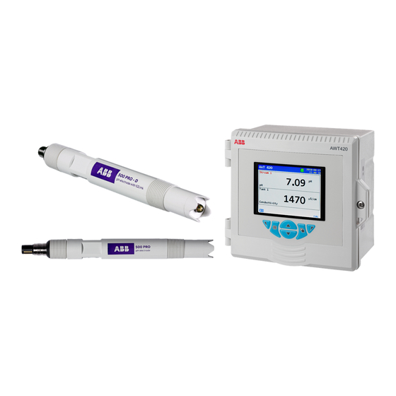
ABB AWT420 Commissioning Instructions
Universal 4-wire, dual-input transmitter
Hide thumbs
Also See for AWT420:
- Operating instruction (110 pages) ,
- Manual (16 pages) ,
- Manual (16 pages)
Table of Contents
Advertisement
—
A B B M E A S U R E M E N T & A N A LY T I C S | C O M M I S S I O N I N G I N S T R U C T I O N
AWT420
Universal 4-wire, dual-input transmitter
Introduction
—
AWT420
Universal 4-wire,
The AWT420 is a universal 4-wire, dual-input
dual-input transmitter
transmitter suitable for the measurement and
control of a wide range of parameters including pH,
ORP, conductivity, turbidity/suspended solids and
dissolved oxygen.
The AWT420 supports both traditional analog and
advanced digital EZLink sensors.
This Commissioning Instruction provides
installation, operation and maintenance procedures
for the AWT420 transmitter. For information on the
sensors, including installation, commissioning,
operation and maintenance procedures, refer to the
specific sensor manual.
Measurement made easy
For more information
Further publications for the AWT420 transmitter
are available for free download from:
www.abb.com/measurement
or by scanning this code:
Links and reference numbers for the transmitter
publications are also shown below:
AWT420 transmitter – Data Sheet
AWT420 transmitter –
Operating Instruction
AWT420 transmitter –
HART Communications Supplement
AWT420 transmitter –
HART FDS Communications Supplement
AWT420 transmitter –
PROFIBUS Communications Supplement
AWT420 transmitter –
MODBUS Communications Supplement
AWT420 transmitter –
Ethernet Communications Supplement
Search for/click on:
DS/AWT420-EN
OI/AWT420-EN
COM/AWT420/
HART-EN
COM/AWT420/
HART/FDS-EN
COM/AWT420/
PROFIBUS-EN
COM/AWT420/
MODBUS-EN
COM/AWT420/
ETHERNET-EN
Advertisement
Table of Contents

Related Manuals for ABB AWT420


Summary of Contents for ABB AWT420
-
Page 1: For More Information
Links and reference numbers for the transmitter This Commissioning Instruction provides publications are also shown below: installation, operation and maintenance procedures Search for/click on: for the AWT420 transmitter. For information on the sensors, including installation, commissioning, AWT420 transmitter – Data Sheet DS/AWT420-EN AWT420 transmitter –... -
Page 2: Table Of Contents
Operator menus ........20 AWT420 transmitter – electrical ....4 Operating modes . - Page 3 Sensor module assemblies ......37 AWT420 pH PCB upgrade/spares kit ..37 AWT420 2-electrode conductivity PCB upgrade/spares kit .
-
Page 4: Health & Safety
AW T4 2 0 | U N I V E R S A L 4 - W I R E , D U A L- I N P U T T R A N S M I T T E R | C I/A W T4 2 0 - E N R E V. B Health & Safety Document symbols Potential safety hazards AWT420 transmitter – electrical Symbols that appear in this document are explained below: WARNING DANGER Bodily injury The signal word ‘DANGER’... -
Page 5: Product Recycling And Disposal
In conformity with European local and national ABB Ltd and its affiliates are not liable for damages and/or regulations, electrical equipment marked with the losses related to such security breaches, any unauthorized... -
Page 6: Overview
AW T4 2 0 | U N I V E R S A L 4 - W I R E , D U A L- I N P U T T R A N S M I T T E R | C I/A W T4 2 0 - E N R E V. B Overview 4 Mechanical installation Transmitter installation The AWT420 is a universal 4-wire single or dual-input transmitter suitable for the measurement and control of a wide Optional accessories range of parameters including pH, ORP, conductivity, turbidity/... -
Page 7: Transmitter Dimensions
AW T4 2 0 | U N I V E R S A L 4 - W I R E , D U A L- I N P U T T R A N S M I T T E R | C I/A W T4 2 0 - E N R E V. B Transmitter dimensions Wall-mounting Dimensions in mm (in) -
Page 8: Panel-Mounting (Optional)
AW T4 2 0 | U N I V E R S A L 4 - W I R E , D U A L- I N P U T T R A N S M I T T E R | C I/A W T4 2 0 - E N R E V. B …4 Mechanical installation …Transmitter installation Panel-mounting (optional) -
Page 9: Pipe-Mounting (Optional)
AW T4 2 0 | U N I V E R S A L 4 - W I R E , D U A L- I N P U T T R A N S M I T T E R | C I/A W T4 2 0 - E N R E V. B Pipe-mounting (optional) Dimensions in mm (in) NOTICE... -
Page 10: Electrical Installation
AW T4 2 0 | U N I V E R S A L 4 - W I R E , D U A L- I N P U T T R A N S M I T T E R | C I/A W T4 2 0 - E N R E V. B 5 Electrical installation DANGER WARNING... -
Page 11: Terminal Connections
Sensor 1 Sensor 2 Sensor module connections Analog output connections (see below for communication module connections) Communication module connections – refer to separate supplements: HART COM/AWT420/HART-EN MODBUS COM/AWT420/MODBUS-EN PROFIBUS COM/AWT420/PROFIBUS-EN ETHERNET COM/AWT420/ETHERNET-EN Main board connections: see below Main board connections... -
Page 12: Digital I/O, Relays And Analog Output Connections
AW T4 2 0 | U N I V E R S A L 4 - W I R E , D U A L- I N P U T T R A N S M I T T E R | C I/A W T4 2 0 - E N R E V. B …5 Electrical installation Digital I/O, relays and analog output connections... -
Page 13: Ph And Conductivity Connections
AW T4 2 0 | U N I V E R S A L 4 - W I R E , D U A L- I N P U T T R A N S M I T T E R | C I/A W T4 2 0 - E N R E V. B pH and conductivity connections pH/ORP/pIon sensor module connections NOTICE... -
Page 14: Power Supply Connection
NOTICE 5 Remove gland cover and route mains power supply cable through it. Electrical installation – ABB recommendations: 6 Route the cable through cable gland and into the • Ferrules are fitted to all cables. enclosure case. • Use M4 ring terminals (crimped) on the earth conductor... - Page 15 AW T4 2 0 | U N I V E R S A L 4 - W I R E , D U A L- I N P U T T R A N S M I T T E R | C I/A W T4 2 0 - E N R E V. B COMMUNICATIONS Sensor 1 version...
-
Page 16: Fitting The Ezlink Modules
AW T4 2 0 | U N I V E R S A L 4 - W I R E , D U A L- I N P U T T R A N S M I T T E R | C I/A W T4 2 0 - E N R E V. B …5 Electrical installation Fitting the EZLink modules Referring to Figure 13:... - Page 17 AW T4 2 0 | U N I V E R S A L 4 - W I R E , D U A L- I N P U T T R A N S M I T T E R | C I/A W T4 2 0 - E N R E V. B Referring to Figure 14: Referring to Figure 15: 7 Fit alignment tab...
-
Page 18: Connecting Ezlink Sensors
Restore defaults is selected from the Configuration/Device NOTICE Setup/Initial Setup menu (see page 29), the ‘Easy Setup’ prompt is displayed: Maximum length of cable from transmitter to sensor(s) – refer to sensor Operating instruction. AWT420 03-09-2019 08:14:45 New TX Referring to Figure 16: Detected... -
Page 19: Operation
AW T4 2 0 | U N I V E R S A L 4 - W I R E , D U A L- I N P U T T R A N S M I T T E R | C I/A W T4 2 0 - E N R E V. B Operation Front panel keys screen. -
Page 20: Modes Of Operation
AW T4 2 0 | U N I V E R S A L 4 - W I R E , D U A L- I N P U T T R A N S M I T T E R | C I/A W T4 2 0 - E N R E V. B …7 Operation Modes of operation Operator menus... -
Page 21: Operating Modes
The remaining 2 Operator pages display values from individual sensors (in sensor order). In Figure 20, Operator page 1 shows that 2 sensors are connected (pH and turbidity). Instrument tag 03-09-2019 (user-assignable) AWT420 Time and date 14:33:12 Sensor tag TAG 1 Chemical units 4.98... - Page 22 Operator Page consecutively. Color-coded sensor tag Process value (PV) • Sensor 1 = red Unit of measure • Sensor 2 = green 03-09-2019 Time and date AWT420 Instrument tag 15:31:08 (user-set) TAG 1 7.82 Parameter ID Color-coded bargraph 17.3...
-
Page 23: View Mode
AW T4 2 0 | U N I V E R S A L 4 - W I R E , D U A L- I N P U T T R A N S M I T T E R | C I/A W T4 2 0 - E N R E V. B View mode Pages displayed in View mode comprise: Chart View... -
Page 24: Log Mode
AW T4 2 0 | U N I V E R S A L 4 - W I R E , D U A L- I N P U T T R A N S M I T T E R | C I/A W T4 2 0 - E N R E V. B …7 Operation Log mode Log entries... -
Page 25: Data Logging
– in this state, Data and Events are lost. 4 To remove the media, if LED is lit, press button • ABB’s DataManager Pro software can be used to store and take the media offline and ensure LED is not lit. -
Page 26: Password Security And Access Level
AW T4 2 0 | U N I V E R S A L 4 - W I R E , D U A L- I N P U T T R A N S M I T T E R | C I/A W T4 2 0 - E N R E V. B 9 Password security and Access Level Setting passwords Access Level... -
Page 27: 10 Sensor Setup
AW T4 2 0 | U N I V E R S A L 4 - W I R E , D U A L- I N P U T T R A N S M I T T E R | C I/A W T4 2 0 - E N R E V. B 10 Sensor setup 2-electrode conductivity Menu... -
Page 28: 2-Electrode Conductivity - Dual Input Calculated Values Setup
AW T4 2 0 | U N I V E R S A L 4 - W I R E , D U A L- I N P U T T R A N S M I T T E R | C I/A W T4 2 0 - E N R E V. B …10 Sensor setup 2-electrode conductivity –... -
Page 29: 4-Electrode Conductivity
AW T4 2 0 | U N I V E R S A L 4 - W I R E , D U A L- I N P U T T R A N S M I T T E R | C I/A W T4 2 0 - E N R E V. B 4-electrode conductivity Menu Comment... -
Page 30: Ph/Redox/Orp
AW T4 2 0 | U N I V E R S A L 4 - W I R E , D U A L- I N P U T T R A N S M I T T E R | C I/A W T4 2 0 - E N R E V. B …10 Sensor setup pH/Redox/ORP Menu... -
Page 31: Rdo
AW T4 2 0 | U N I V E R S A L 4 - W I R E , D U A L- I N P U T T R A N S M I T T E R | C I/A W T4 2 0 - E N R E V. B Menu Comment Default... -
Page 32: 11 Specification
AW T4 2 0 | U N I V E R S A L 4 - W I R E , D U A L- I N P U T T R A N S M I T T E R | C I/A W T4 2 0 - E N R E V. B 11 Specification Operation Display... -
Page 33: Connectivity/Communications (Optional)
AW T4 2 0 | U N I V E R S A L 4 - W I R E , D U A L- I N P U T T R A N S M I T T E R | C I/A W T4 2 0 - E N R E V. B Connectivity/Communications (optional) 2-electrode conductivity Ethernet... -
Page 34: 4-Electrode Conductivity
AW T4 2 0 | U N I V E R S A L 4 - W I R E , D U A L- I N P U T T R A N S M I T T E R | C I/A W T4 2 0 - E N R E V. B …11 Specification 4-electrode conductivity pH/ORP (Redox) -
Page 35: Ezlink
Class B digital device, pursuant to part 15 of Bluetooth the FCC Rules. These limits are designed to provide The Bluetooth Low Energy Module within the AWT420 reasonable protection against harmful interference in a transmitter has received the regulatory approval for the residential installation. - Page 36 • Taiwan/NCC No: CCAN16LP0011T7 Taiwan CCAN16LP0011T7 注意 ! 依據 低功率電波輻射性電機管理辦法 第十二條 經型式認證合格之低功率射頻電機, 非經許可, 公司、 商號或使用者均不得擅自變更頻率、 加大 功率或變更原設計 之特性及功能。 第十四條 低功率射頻電機之使用不得影響飛航安 全及干擾合法通信 ; 經發現有干擾現象時, 應立即停用, 並改善至無 干擾時方得繼續使用。 前項合法通信, 指依電信規定作業之無線電信。 低功率射頻電機須忍受合法通信或工業、 科學及 醫療用電波輻射性 電機設備之干擾。 DS/AWT420-EN Rev. A...
-
Page 37: Spares
Communications module assemblies AWT420 pH/ORP PCB upgrade/spares kit AWT420 HART PCB upgrade/spares kit Part number Part number 3KXA877420L0014 3KXA877420L0051 AWT420 2-electrode conductivity PCB upgrade/spares kit AWT420 Profibus PCB upgrade/spares kit Part number Part number 3KXA877420L0013 3KXA877420L0052 AWT420 4-electrode conductivity PCB upgrade/spares kit... -
Page 38: Mounting Kits
AW T4 2 0 | U N I V E R S A L 4 - W I R E , D U A L- I N P U T T R A N S M I T T E R | C I/A W T4 2 0 - E N R E V. B …12 Spares Mounting kits Gland packs/EZLink connectors... - Page 39 AW T4 2 0 | U N I V E R S A L 4 - W I R E , D U A L- I N P U T T R A N S M I T T E R | C I/A W T4 2 0 - E N R E V. B Acknowledgments •...
- Page 40 We reserve the right to make technical changes or modify the contents of this document without prior notice. With regard to purchase orders, the agreed particulars shall prevail. ABB does not accept any responsibility whatsoever for potential errors or possible lack of information in this document.
Need help?
Do you have a question about the AWT420 and is the answer not in the manual?
Questions and answers