Siemens SINUMERIK 828D Series Software And Hardware Service Manual
Hide thumbs
Also See for SINUMERIK 828D Series:
- Function manual (1799 pages) ,
- Commissioning manual (1167 pages) ,
- Operating manual (926 pages)
Table of Contents
Advertisement
SINUMERIK
SINUMERIK 828D
Software and hardware
Service Manual
Valid for:
SINUMERIK 828D PPU 27x.4
SINUMERIK 828D PPU 290.4
CNC system software V4.8 SP4
08/2018
6FC5397-5DP40-6BA1
Preface
Fundamental safety
instructions
System description
Service cases - software
Service cases - hardware
Spare parts and accessories
Appendix
1
2
3
4
5
A
Advertisement
Table of Contents

Subscribe to Our Youtube Channel
Related Manuals for Siemens SINUMERIK 828D Series


Summary of Contents for Siemens SINUMERIK 828D Series
- Page 1 Preface Fundamental safety instructions System description SINUMERIK Service cases - software SINUMERIK 828D Software and hardware Service cases - hardware Spare parts and accessories Service Manual Appendix Valid for: SINUMERIK 828D PPU 27x.4 SINUMERIK 828D PPU 290.4 CNC system software V4.8 SP4 08/2018 6FC5397-5DP40-6BA1...
- Page 2 Note the following: WARNING Siemens products may only be used for the applications described in the catalog and in the relevant technical documentation. If products and components from other manufacturers are used, these must be recommended or approved by Siemens. Proper transport, storage, installation, assembly, commissioning, operation and maintenance are required to ensure that the products operate safely and without any problems.
-
Page 3: Preface
Siemens' content, and adapt it for your own machine documentation. Training At the following address (http://www.siemens.com/sitrain), you can find information about SITRAIN (Siemens training on products, systems and solutions for automation and drives). FAQs You can find Frequently Asked Questions in the Service&Support pages under Product Support (https://support.industry.siemens.com/cs/de/en/ps/faq). - Page 4 Note regarding the General Data Protection Regulation Siemens observes standard data protection principles, in particular the principle of privacy by design. That means that this product does not process / store any personal data, only technical functional data (e.g. time stamps). If a user links this data with other data (e.g. a shift schedule) or stores personal data on the same storage medium (e.g.
-
Page 5: Table Of Contents
Table of contents Preface.................................3 Fundamental safety instructions.........................11 General safety instructions.....................11 Equipment damage due to electric fields or electrostatic discharge........15 Warranty and liability for application examples..............16 Industrial security........................17 Residual risks of power drive systems...................19 System description.............................21 System overview........................21 PPU versions.........................24 Service cases - software..........................27 Backing up user data......................29 3.1.1 This is how you backup user data..................29... - Page 6 Table of contents Service and diagnostics......................78 3.8.1 Backing up log data for service case..................78 3.8.1.1 Overview..........................78 3.8.1.2 Backing up log data to USB....................78 3.8.1.3 Backing up log data as ZIP file....................78 Service cases - hardware...........................79 Safety instructions for the hardware..................81 PPU 27x.4..........................83 4.2.1 PPU status displays.......................83...
- Page 7 Table of contents 4.9.2 CU320-2 PN connections.....................127 4.9.3 This is how you remove the CU320-2 PN................128 4.9.4 This is how you install the CU320-2 PN................129 4.9.5 CU310-2 PN status displays....................129 4.9.6 CU310-2 PN connections.....................133 4.9.7 This is how you remove the CU310-2 PN................134 4.9.8 This is how you install the CU310-2 PN................136 4.10...
- Page 8 Table of contents 4.16.1 SMC10/SMC20 status displays....................202 4.16.2 SMC10/SMC20 connections....................203 4.16.3 This is how you remove an SMC10/SMC20................203 4.16.4 This is how you install an SMC10/SMC20................205 4.16.5 SMC30 status displays......................206 4.16.6 SMC30 connections......................207 4.16.7 This is how you remove an SMC30..................207 4.16.8 This is how you install an SMC30..................209 4.16.9...
- Page 9 Table of contents Index.................................245 Software and hardware Service Manual, 08/2018, 6FC5397-5DP40-6BA1...
- Page 10 Table of contents Software and hardware Service Manual, 08/2018, 6FC5397-5DP40-6BA1...
-
Page 11: Fundamental Safety Instructions
Fundamental safety instructions General safety instructions WARNING Electric shock and danger to life due to other energy sources Touching live components can result in death or severe injury. ● Only work on electrical devices when you are qualified for this job. ●... - Page 12 Fundamental safety instructions 1.1 General safety instructions WARNING Electric shock due to equipment damage Improper handling may cause damage to equipment. For damaged devices, hazardous voltages can be present at the enclosure or at exposed components; if touched, this can result in death or severe injury.
- Page 13 ● If you come closer than around 2 m to such components, switch off any radios or mobile phones. ● Use the "SIEMENS Industry Online Support app" only on equipment that has already been switched off. WARNING...
- Page 14 Fundamental safety instructions 1.1 General safety instructions WARNING Malfunctions of the machine as a result of incorrect or changed parameter settings As a result of incorrect or changed parameterization, machines can malfunction, which in turn can lead to injuries or death. ●...
-
Page 15: Equipment Damage Due To Electric Fields Or Electrostatic Discharge
Fundamental safety instructions 1.2 Equipment damage due to electric fields or electrostatic discharge Equipment damage due to electric fields or electrostatic discharge Electrostatic sensitive devices (ESD) are individual components, integrated circuits, modules or devices that may be damaged by either electric fields or electrostatic discharge. NOTICE Equipment damage due to electric fields or electrostatic discharge Electric fields or electrostatic discharge can cause malfunctions through damaged individual... -
Page 16: Warranty And Liability For Application Examples
Fundamental safety instructions 1.3 Warranty and liability for application examples Warranty and liability for application examples Application examples are not binding and do not claim to be complete regarding configuration, equipment or any eventuality which may arise. Application examples do not represent specific customer solutions, but are only intended to provide support for typical tasks. -
Page 17: Industrial Security
Siemens’ products and solutions undergo continuous development to make them more secure. Siemens strongly recommends that product updates are applied as soon as they are available and that the latest product versions are used. Use of product versions that are no longer supported, and failure to apply the latest updates may increase customer’s exposure to cyber... - Page 18 Fundamental safety instructions 1.4 Industrial security WARNING Unsafe operating states resulting from software manipulation Software manipulations (e.g. viruses, trojans, malware or worms) can cause unsafe operating states in your system that may lead to death, serious injury, and property damage. ●...
-
Page 19: Residual Risks Of Power Drive Systems
Fundamental safety instructions 1.5 Residual risks of power drive systems Residual risks of power drive systems When assessing the machine- or system-related risk in accordance with the respective local regulations (e.g., EC Machinery Directive), the machine manufacturer or system installer must take into account the following residual risks emanating from the control and drive components of a drive system: 1. - Page 20 Fundamental safety instructions 1.5 Residual risks of power drive systems Software and hardware Service Manual, 08/2018, 6FC5397-5DP40-6BA1...
-
Page 21: System Description
System description System overview Configuration with four axes (basic configuration) The following configuration shows a typical example with SINAMICS S120 booksize: Figure 2-1 Configuration example 1: Basic configuration with four axes Software and hardware Service Manual, 08/2018, 6FC5397-5DP40-6BA1... - Page 22 System description 2.1 System overview Configuration with 4 axes and 2 auxiliary axes The following configuration shows an example with 2 auxiliary axes: Figure 2-2 Configuration example 2: Basic expansion stage with 4 axes and 2 auxiliary axes Software and hardware Service Manual, 08/2018, 6FC5397-5DP40-6BA1...
- Page 23 System description 2.1 System overview Configuration with 6 axes (maximum expansion stage) and Safety Integrated The following configuration shows the maximum expansion stage with SINAMICS S120 Combi: Figure 2-3 Configuration example 3: Maximum expansion stage with 6 axes and with Safety Integrated Software and hardware Service Manual, 08/2018, 6FC5397-5DP40-6BA1...
-
Page 24: Ppu Versions
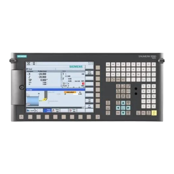
System description 2.2 PPU versions PPU versions Front of the PPU 290.4 ① USB interface ② X127 Ethernet interface (service connection) ③ Qwerty keyboard ④ Keys to quickly select the operating area ⑤ Cursor keypad ⑦ Numerical keys ⑥ ⑧ Control keys Software and hardware Service Manual, 08/2018, 6FC5397-5DP40-6BA1... - Page 25 System description 2.2 PPU versions Front of the PPU 27x.4 ① ⑧ 3/8" threads for additional components Proximity sensor ② ⑨ Front cover Numerical keys ③ ⑩ QWERTY keyboard Status LED: RDY, NC, CF ④ ⑦ ⑪ Control keys Slot for CompactFlash card ⑤...
- Page 26 System description 2.2 PPU versions Rear of the PPU ①② X122, X132 Digital inputs/outputs, drive ③④ X242, X252 Digital inputs/outputs for NC; control of the analog spindle (X252) ⑤ X143 Handwheels ⑥ M, T2, T1, T0 Measuring sockets ⑦ Power supply ⑧...
-
Page 27: Service Cases - Software
The directory contains all of the logbook and debug information available in the system. Contact Technical Support Contact to technical support: www.siemens.com/sinumerik/help (www.siemens.com/sinumerik/help) To ensure fast processing, please provide the following information: ● Alarm number with alarm text ● Description of the operator action/operating mode prior to the alarm message ●... - Page 28 Service cases - software Field service, services and local contacts: www.siemens.com/sinumerik/contact (http://www.siemens.com/sinumerik/contact) SINUMERIK documentation: www.siemens.com/sinumerik/docu (http://www.siemens.com/sinumerik/docu) Further information: www.siemens.com/sinumerik/support (http://www.siemens.com/sinumerik/support) Siemens Industry Online Support provides further information, such as FAQs, product information, forum contributions. Software and hardware Service Manual, 08/2018, 6FC5397-5DP40-6BA1...
-
Page 29: Backing Up User Data
Service cases - software 3.1 Backing up user data Backing up user data 3.1.1 This is how you backup user data Application A backup of the NC data memory is generated using the "Save data" function. The NC data backup must be performed for every control that has been commissioned in order to be able to quickly restore the control system in the case of data loss. - Page 30 Service cases - software 3.1 Backing up user data 4. This is followed by the "Query" to backup data: Software and hardware Service Manual, 08/2018, 6FC5397-5DP40-6BA1...
- Page 31 An archive is created that contains the version-dependent commissioning data from the NC and PLC and is then stored under the following directory on the system CompactFlash card: /siemens/sinumerik/sys_cache/archive/savedata.ard The archive is overwritten with a new version every time the "Save data" button is pressed.
-
Page 32: This Is How You Load The User Data Backup
Service cases - software 3.1 Backing up user data The automatic data backup is loaded in the following cases: 1. New hardware components are identified when the software is started up again following a hardware replacement, such as if the system CompactFlash card is operated in a replacement PPU. - Page 33 Service cases - software 3.1 Backing up user data Procedure To load the manual data backup (via the "Back up data" softkey), proceed as follows: 1. The following display is shown when booting after power-on: 2. To start the Startup menu press the <SELECT> key. You now go to the Startup menu: Software and hardware Service Manual, 08/2018, 6FC5397-5DP40-6BA1...
- Page 34 Service cases - software 3.1 Backing up user data 3. Using the arrow key, select the menu item "Reload saved user data". 4. Confirm that the backup is loaded by pressing the key <INPUT>. 5. Confirm the confirmation prompt by pressing the <INPUT> key. Are you sure you want to reload saved user data?"...
-
Page 35: Generating A Commissioning Archive
Service cases - software 3.2 Generating a commissioning archive Generating a commissioning archive Overview A commissioning archive is used to completely backup all of the data required for the machine function. Note Data must always be backed up before a machine is delivered. Only then can it be ensured that in the case of service, the delivery condition of the machine can be restored. - Page 36 Easy Archive ● Select all of the components, unless it is known that individual components do not deviate from the Siemens standard. ● Select all data classes, unless only certain data (e.g. INDIVIDUAL) are to be backed up. 6. Press the "OK" softkey to create the archive.
- Page 37 Service cases - software 3.2 Generating a commissioning archive 8. Select a directory. Example: User CF - OR - 9. Press the "New directory" softkey to generate a new directory. The "New Directory" window opens. 10.Enter the required name and confirm with "OK." The directory is created subordinate to the selected folder.
-
Page 38: This Is How You Read A Setup Archive From An External Data Storage Medium
Service cases - software 3.2 Generating a commissioning archive 3.2.2 This is how you read a setup archive from an external data storage medium Reading in an archive from an external data carrier Procedure: 1. Select the "Startup" operating area. 2. - Page 39 Service cases - software 3.2 Generating a commissioning archive 7. Select the required setup archive (ARD). Example: User CF 8. Press "OK". A query is displayed, here you can see the most important data of the selected archive to be certain that it is OK. 9.
-
Page 40: This Is How You Generate A Setup Archive On The System Compactflash Card
Service cases - software 3.2 Generating a commissioning archive 3.2.3 This is how you generate a setup archive on the system CompactFlash card Generating an archive on the system CompactFlash Card Procedure: 1. Select the "Startup" operating area. 2. Press the menu forward key. 3. -
Page 41: This Is How You Read In A Setup Archive From The System Compactflash Card
Easy Archive ● Select all of the components, unless it is known that individual components do not deviate from the Siemens standard. ● Select all data classes, unless only certain data (e.g. INDIVIDUAL) are to be backed up. 6. Press the "OK" softkey to create an archive. - Page 42 Service cases - software 3.2 Generating a commissioning archive Procedure: 1. Select the "Startup" operating area. 2. Press the menu forward key. 3. Press the "Setup archive" softkey. 4. Press "OK". The "Create setup archive" window opens. 5. Activate "Read in setup archive". 6.
- Page 43 Service cases - software 3.2 Generating a commissioning archive 7. Select the required setup archive (ARD). Example: "Archives" → "Manufacturer" 8. Press "OK". A window with the data of the selected archive is displayed. 9. Data is read in when pressing "OK". 10.In the case of errors or problems, import can be terminated by pressing the "Cancel"...
-
Page 44: Software Backup
Service cases - software 3.3 Software backup Software backup 3.3.1 This is how you generate a software backup Overview With "Create software backup", a function is provided to generate a backup of the system software including all of the user data saved on the system card. This backup represents the "Backup"... - Page 45 Service cases - software 3.3 Software backup 1. Press the <SELECT> key, "Normal startup" is the default setting. 2. To call the "Startup menu", press the following keys in succession: Menu reset key, HSK2 (horizontal SK2), VSK2 (vertical SK2) Note PPU with touch operation To call the startup menu when powering up, there is an additional shortcut for all PPUs: "8"...
- Page 46 Service cases - software 3.3 Software backup 1. Press the <INPUT> key to start the backup. The software first checks whether a backup was already generated on the card and outputs a message. The backup can now be overwritten or the process interrupted by making the appropriate operator action.
-
Page 47: This Is How You Install A Software Backup
Service cases - software 3.3 Software backup 3. Wait until the following message is displayed: 4. Withdraw the storage medium from the slot at the front panel of the control. 5. Switch the control off. 6. Switch the control on. 7. - Page 48 Service cases - software 3.3 Software backup Installing the software backup Procedure: 1. Switch-on the control again, as the backup can only be generated when the control boots. After the control has been switched-on, the following is displayed: 1. Press the <SELECT> key, "Normal startup" is the default setting. 2.
- Page 49 Service cases - software 3.3 Software backup 4. Using the cursor keys, select the menu item "Install software update/backup". 5. Press the <INPUT> key to confirm your selection: 6. Insert the storage medium with the backup in the slot and confirm with "Yes" by using the cursor keys to make the selection: Software and hardware Service Manual, 08/2018, 6FC5397-5DP40-6BA1...
- Page 50 Service cases - software 3.3 Software backup 7. Select the valid backup using the cursor keys. 8. Press the <Input> key to confirm your selection. 9. The following message briefly appears: "Starting software update" Then the screen goes dark for several seconds. 10.If a valid backup has been found, the following message is output: If a valid backup was not selected, then the upgrade is canceled with the following message: "Image file is corrupt!"...
- Page 51 Service cases - software 3.3 Software backup 14.Switch the control on. 15.The control boots normally. Note If the procedure is interrupted, then it must be restarted. If the system CompactFlash Card is no longer identified as a bootable CompactFlash Card, then a boot system must be generated on this card.
-
Page 52: Updating The Software
Service cases - software 3.4 Updating the software Updating the software Data backup If a system update is necessary, then the system data must be backed up so that no data is lost in the case of a problem. In this case, we recommend to perform two types of data backup. 1. - Page 53 Service cases - software 3.4 Updating the software 1. Press the <SELECT> key, "Normal startup" is the default setting. 2. To call the "Startup menu", press the following keys in succession: Menu reset key, HSK2 (horizontal SK2), VSK2 (vertical SK2) Note PPU with touch operation To call the startup menu when powering up, there is an additional shortcut for all PPUs: "8"...
- Page 54 Service cases - software 3.4 Updating the software 6. Use the cursor keys to select "Yes". 7. Select the update image (*.tgz) on the storage medium and confirm with <INPUT>. 8. The software update is started: The following message appears while the update is running: Software and hardware Service Manual, 08/2018, 6FC5397-5DP40-6BA1...
- Page 55 Service cases - software 3.4 Updating the software 9. Wait until the following message is output: 10.Withdraw the storage medium from the slot. 11.Switch the control off. 12.Switch the control on. 13.The control boots normally. Note If the update is interrupted, then it must be restarted. If the system CompactFlash Card is no longer identified as bootable system, then a boot system must be generated on this card (see also: This is how you create a boot system (Page 56)).
-
Page 56: Generating A Boot System On The Compactflash Card
PC/PG. 3.5.1 This is how you create a boot system Precondition The default path to install the boot system is: C:\Program Files (x86)\Siemens\Toolbox 828D\V04070xx00\RecoverySys The file name of the boot system is: minsys.img Software and hardware Service Manual, 08/2018, 6FC5397-5DP40-6BA1... - Page 57 Service cases - software 3.5 Generating a boot system on the CompactFlash card With SINUMERIK Integrate Access MyMachine /P2P, the minsys.img file is copied to an empty replacement card. Precondition to write: ● SINUMERIK Integrate Access MyMachine /P2P is installed. ●...
- Page 58 Service cases - software 3.5 Generating a boot system on the CompactFlash card 6. All of the identified interchangeable drives are displayed, here in the example, the CompactFlash Card is identified as drive F:\. 7. Confirm the selection of the target drive with "OK". By pressing the "Write" button, the image is transferred to the target drive.
-
Page 59: This Is How You Install A Software Backup Using The Boot System
Service cases - software 3.5 Generating a boot system on the CompactFlash card 3.5.2 This is how you install a software backup using the boot system Overview If a CompactFlash Card with a boot system is used as system CompactFlash Card, the system software or a previously generated software backup must still be transferred. - Page 60 Service cases - software 3.5 Generating a boot system on the CompactFlash card 3. Confirm the question with "Yes". 4. Insert the CompactFlash Card or a USB-FlashDrive with the image into the slot on the front panel of the control. 5.
- Page 61 Service cases - software 3.5 Generating a boot system on the CompactFlash card 7. If a valid image has been found, the following message is output: 8. Wait until the following message is displayed: 9. Switch the control off. 10.Switch the control system back on again: The control boots normally. Note If the system was booted using a boot system, there is no valid license key on the system CompactFlash Card.
-
Page 62: Licensing
Service cases - software 3.6 Licensing Licensing 3.6.1 Licensing after replacing the system CompactFlash Card Application The license key of the SINUMERIK 828D is linked with the system CompactFlash Card. If the system CompactFlash Card is replaced for a SINUMERIK 828D, the license key loses its validity and the system is only ready with some significant restrictions. - Page 63 Service cases - software 3.6 Licensing Proceed as follows to access the "licenses" dialog box: 1. Select the "Startup" operating area. 2. Press the menu forward key. 3. Press the "Licenses" softkey. The "Licensing" window opens. Using the vertical softkeys, you can execute the following actions: –...
-
Page 64: This Is How You Determine Missing Licenses/Options
To conclude the assignment, the license key must be entered at the control via the user interface. See also The license database administered by Siemens can only be accessed using the Web License Manager (http://www.siemens.com/automation/license). Note The NC start function is suppressed if a CNC option, for which no valid license key has been entered, is additionally activated. -
Page 65: This Is How You Generated A New License Key
Service cases - software 3.6 Licensing 3. Press the "Missing lic./opt." softkey in order to display all options that are licensed. In the "Set" column, you can deselect the options that you do not require. Figure 3-3 Licensing (example) 4. Press the softkey "Set option according to license", to activate all of the options contained in the license key. - Page 66 3. Press the "Licenses" softkey. 4. Press the "Overview" softkey and note down the serial number of the system CompactFlash Card. 5. At your PG/PC, establish a connection to the Web License Manager (http:// www.siemens.com/automation/license) Software and hardware Service Manual, 08/2018, 6FC5397-5DP40-6BA1...
- Page 67 Service cases - software 3.6 Licensing 6. Log on via "Direct access". Follow additional instructions in the Web License Manager: 7. After completing the assignment process, enter the license key displayed in the Web License Manager into the "Licensing" dialog box in SINUMERIK Operate. Note License key via e-mail If you have an e-mail address, you have the option (checkbox) of receiving the license key...
-
Page 68: This Is How You Display The Actual License Key
Service cases - software 3.6 Licensing 4. Press the "Overview” softkey. If you receive the license key via the Web License Manager, enter the license key manually in the field "You can enter a new license key here". 5. Press the <INPUT> key. If the license key is valid, the message "License key set"... - Page 69 Service cases - software 3.6 Licensing Displaying the actual license key in the Internet In order to view the actual license key of the control, using the serial number, it is possible display the license key via the Internet. The serial number is on the system CompactFlash Card - or can be displayed at the control as described above.
- Page 70 Service cases - software 3.6 Licensing 4. In the menu, select "Hardware serial number" and enter the serial number of the system CompactFlash Card. 5. Press the "Display license key" softkey. 6. The actual license key is displayed as follows: Software and hardware Service Manual, 08/2018, 6FC5397-5DP40-6BA1...
-
Page 71: Machine Registration
● Send the machine identity On-site service (OSS) SINUMERIK 828D and the associated drive, motor and accessories from Siemens include an on-site service (local service) for 24 months. The on-site service time is extended to 36 months by registering the machine. - Page 72 Service cases - software 3.7 Machine registration During a service call, the data should be checked as to whether it is correct. Open the "Machine identity" dialog box Procedure: 1. Select the "Diagnostics" operating area using the following key: 2. Press the "Version" softkey to open the "Version data" dialog box. 3.
-
Page 73: This Is How You Make A New Entry In The Logbook
Note Contact data Using the "Import data" softkey, templates with contact data can be imported to simplify data entry; these templates are available through Siemens sales partners. 3.7.2 This is how you make a new entry in the logbook Generating a new logbook entry In order to log service and diagnostic procedures at the machine, make an entry in the machine logbook. - Page 74 Service cases - software 3.7 Machine registration To make a logbook entry, proceed as follows: 1. Select the "Diagnostics" operating area using the following key: 2. Press the "Version" softkey. 3. Press the "Logbook" softkey. 4. Press the "New entry" softkey in order to make an entry in the logbook. Complete the fields for the new logbook entry: 5.
-
Page 75: This Is How You Save The Machine Identity
Service cases - software 3.7 Machine registration For the following activities, two additional softkeys are available, which generate pre- configured logbook entries: 1st Commissioning completed (commissioning at the machine OEM's fa‐ cility) 2nd commissioning completed (commissioning at the company operating the machine/end user) Note Once saved, data can no longer be changed. - Page 76 Service cases - software 3.7 Machine registration 4. Press the "OK" softkey. The data are pre-assigned so that a change is not necessary. The "Name" text field is pre-assigned as follows: <Machine name/Number>+<Number of the CompactFlash Card> You now have the opportunity of changing this name. You can enter a comment in the "Comments"...
-
Page 77: This Is How You Send The Machine Identity
You can find instructions on how to transfer data on this Internet page. Follow these instructions. Note Contact persons worldwide If it was not possible to transfer the file, then please contact your local Siemens contact person (http://www.automation.siemens.com/partner) in sales. Software and hardware Service Manual, 08/2018, 6FC5397-5DP40-6BA1... -
Page 78: Service And Diagnostics
Service cases - software 3.8 Service and diagnostics Service and diagnostics 3.8.1 Backing up log data for service case 3.8.1.1 Overview If system problems occur, it is necessary to back up all of the existing log files to provide them to the hotline for diagnostics. -
Page 79: Service Cases - Hardware
Service cases - hardware Components in the control cabinet The sequence in the chapter of the hardware components corresponds to the following systematics: ● Components at the machine ● Components in the control cabinet Figure 4-1 Components in the control cabinet Software and hardware Service Manual, 08/2018, 6FC5397-5DP40-6BA1... - Page 80 Service cases - hardware Figure 4-2 Supplementary components in the electrical cabinet References Information about the cause of faults and how they can be resolved can be found in the following references: ● SINUMERIK 828D/SINAMICS S120 Diagnostics Manual "Alarms" ● SINUMERIK 828D/SINAMICS S120 List Manual "Parameter description" ●...
-
Page 81: Safety Instructions For The Hardware
Service cases - hardware 4.1 Safety instructions for the hardware Safety instructions for the hardware WARNING Danger to life if the fundamental safety instructions and remaining risks are not carefully observed The non-observance of the fundamental safety instructions and residual risks stated in Chapter 1 can result in accidents with severe injuries or death. - Page 82 Service cases - hardware 4.1 Safety instructions for the hardware NOTICE Damage through electric fields or electrostatic discharge Electric fields or electrostatic discharge can cause malfunctions through damaged individual components, integrated circuits, modules or devices. ● Only pack, store, transport and send electronic components, modules or devices in their original packaging or in other suitable materials, e.g conductive foam rubber of aluminum foil.
-
Page 83: Ppu 27X.4
Service cases - hardware 4.2 PPU 27x.4 PPU 27x.4 4.2.1 PPU status displays Status displays front side On the front side of the PPU, the following status displays provide information about the module state: Figure 4-3 Vertical flap (detail) LEDs and the slots for the CompactFlash card are not available on the front of the PPU 27x. The three LEDs located behind the front flap at the front of the PPU have the following significance: Name... - Page 84 Service cases - hardware 4.2 PPU 27x.4 The RJ45 socket is equipped with one green and one yellow LED. As a consequence, the following information of the PLC I/O interface is displayed based on PROFINET: Name Color State Meaning Link Green 100 MBit link available Missing or faulty link...
-
Page 85: This Is How You Remove The Ppu
Service cases - hardware 4.2 PPU 27x.4 Name Color State Meaning Activity Yellow Sending or receiving No activity There are 2 additional LEDs "FAULT" and "SYNC" next to port 1, which apply to both ports: Name Color State Meaning FAULT For the maximum expansion level of the PLC I/O: The data ex‐... -
Page 86: This Is How You Install The Ppu
Service cases - hardware 4.2 PPU 27x.4 4. Label all connectors/cables that are inserted in the module. Only then, can it be ensured that the cables are not interchanged. 5. Withdraw the power supply X1. 6. Withdraw the digital input/output terminals X122, X132, X142. 7. - Page 87 Service cases - hardware 4.2 PPU 27x.4 Procedure: 1. Now, install the system CompactFlash Card into the new PPU. (refer to Chapter This is how you insert the system CompactFlash Card (Page 89)) 2. Insert the PPU into the installation cutout from the front. 3.
-
Page 88: Replacing The System Compactflash Card
Service cases - hardware 4.3 Replacing the system CompactFlash Card Replacing the system CompactFlash Card 4.3.1 This is how you remove the system CompactFlash Card Overview If service is required, it may be necessary to replace the system CompactFlash Card of the control. -
Page 89: This Is How You Insert The System Compactflash Card
Service cases - hardware 4.3 Replacing the system CompactFlash Card 3. Move the metal cover to the side and remove it. 4. Remove the system CompactFlash Card from the side. 5. First, guide the metal cover at the rear into the rabbet and fix to the housing using the screw. 4.3.2 This is how you insert the system CompactFlash Card Precondition... - Page 90 Service cases - hardware 4.3 Replacing the system CompactFlash Card Inserting the system CompactFlash Card Note When inserting the system CompactFlash Card, carefully ensure that neither the screw nor the system CompactFlash Card falls into the PPU or the machine. Procedure: 1.
-
Page 91: Replacing The Front Cover
Service cases - hardware 4.4 Replacing the front cover Replacing the front cover 4.4.1 This is how you remove the front cover Precondition You must first remove the PPU before you remove the front cover, see This is how you remove the PPU (Page 85). -
Page 92: This Is How You Install The Front Cover
Service cases - hardware 4.4 Replacing the front cover 4.4.2 This is how you install the front cover Installing the front cover Procedure: 1. Insert the springs and pins into the front cover. Spring Cover Spring 2. Press in the pins and mount the front cover. The pins must snap into the PPU housing. After you have installed the front cover, you can also possibly reinstall the PPU, see This is how you install the PPU (Page 86). -
Page 93: Machine Control Panels
Service cases - hardware 4.5 Machine control panels Machine control panels 4.5.1 This is how you remove MCP 483 USB/MCP 310 USB/MCP 416 USB Removing If the machine control panel has a hardware defect, then it must be replaced by an identical replacement part. - Page 94 Service cases - hardware 4.5 Machine control panels ① Interface X51, X52, X55 ② Protective conductor connection ③ Slots for control devices (d = 16 mm) ④ USB connection for communication with the PPU Figure 4-5 MCP 310 USB interfaces ①...
-
Page 95: This Is How You Install The Mcp 483 Usb/Mcp 310 Usb/Mcp 416 Usb
Service cases - hardware 4.5 Machine control panels ① USB connection for communication with the PPU ② Protective conductor connection ③ Interface X51, X52, X55 ④ Slot for the Emergency Stop button ⑤ Slots for control devices (d = 16 mm) Figure 4-7 MCP 416 USB interfaces 4.5.2... -
Page 96: Status Display Mcp Interface Pn
Service cases - hardware 4.5 Machine control panels 4.5.3 Status display MCP interface PN LEDs for status display For the MCP interface PN, the following LEDs provide information about the module status: Figure 4-8 Status display Meaning of the LED H500 H501 H502 (red) - Page 97 Service cases - hardware 4.5 Machine control panels 24 VDC power supply X2 / X3 PROFINET interfaces Interface for rotary switch feed override Interface for rotary switch spindle override X40/X41 Digital inputs (24 V) X51 / X52 / X55 Digital inputs (TTL) X58 / X57 / X56 / X53 / Digital outputs (24 V) X60 / X62...
-
Page 98: This Is How You Install The Mcp Interface Pn
Service cases - hardware 4.5 Machine control panels 5. Release the strain relief of the Ethernet cables. 6. Remove the Ethernet cables from interface X2/X3 (port 1/port 2). 7. Release other cables (e.g. rotary switch cable or cables for digital inputs and outputs), if available. -
Page 99: Status Displays, Mcp 483C Pn
Service cases - hardware 4.5 Machine control panels The handwheel signal transfer type is set using switch S2-1. S2-1 Meaning Differential connection TTL interface Note Switch S2-2 is reserved for test purposes. 4.5.6 Status displays, MCP 483C PN LED status displays For the MCP 483C PN there are 3 LEDs in a row (H1 - H3), which provide information about the module state: Figure 4-10... -
Page 100: This Is How You Remove The Mcp 483C Pn
Service cases - hardware 4.5 Machine control panels 4.5.7 This is how you remove the MCP 483C PN Overview The activities that must be taken into account when replacing a machine control panel are subsequently described. If the machine control panel has a hardware defect, then it must be replaced by an identical replacement part. - Page 101 Service cases - hardware 4.5 Machine control panels Removing ① Ground terminal ② Feedrate override ③ Spindle override ④ Port 1: Connection: PLC I/O interface based on PROFINET Port 2: Connection: PLC I/O interface based on PROFINET ⑤ Slot for Emergency Stop ⑥...
-
Page 102: This Is How You Install The Mcp 483C Pn
Service cases - hardware 4.5 Machine control panels 4. If it has not already been done, label all connectors that lead to the module now. Only then, can it be ensured that the cables are not interchanged. ⑭ 5. Withdraw the power supply X10 ( ⑨... -
Page 103: Status Displays Mcp 310C Pn
Service cases - hardware 4.5 Machine control panels Figure 4-12 Switch S2 Switch S2 defines the IP address of the machine control panel: Device name PROFINET address "64" For SINUMERIK 828D, the IP address = 192.168.214.64 must always be assigned to the MCP. 4.5.9 Status displays MCP 310C PN LEDs for status display... -
Page 104: This Is How You Remove The Mcp 310C Pn
Service cases - hardware 4.5 Machine control panels 4.5.10 This is how you remove the MCP 310C PN Overview The activities that must be taken into account when replacing a machine control panel are subsequently described. If the machine control panel has a hardware defect, then it must be replaced by an identical replacement part. - Page 105 Service cases - hardware 4.5 Machine control panels Removing ① Slot for Emergency Stop button or spindle override ② Power supply interface ③ Handwheel connection ④ Reserved ⑤ Switch for setting the handwheel signal type ⑥ Switch for setting the MCP address ⑦...
-
Page 106: This Is How You Install The Mcp 310C Pn
Service cases - hardware 4.5 Machine control panels 4. If it has not already been done, label all connectors that lead to the module now. Only then, can it be ensured that the cables are not interchanged. ② 5. Withdraw the power supply X10 ( ⑧... -
Page 107: This Is How You Replace The Rotary Switch
Service cases - hardware 4.5 Machine control panels Switch S2 Figure 4-15 Switch S2 Switch S2 defines the IP address of the machine control panel: Device name PROFINET address "64" For SINUMERIK 828D, the IP address = 192.168.214.64 must always be assigned to the MCP. 4.5.12 This is how you replace the rotary switch Overview... - Page 108 Service cases - hardware 4.5 Machine control panels Removing a rotary switch Procedure: ③ ② 1. Pry off the cap from the knob (snap on connection!). ① 2. Remove the nut of collet with a wrench (size 10). ② 3. Remove the complete knob ⑤...
- Page 109 Service cases - hardware 4.5 Machine control panels ② 8. Place the cap on the knob and snap it into position. ⑦ 9. Fold and fasten the connecting cable as shown in the diagram on the right. ① O-ring Detail diagram of the connector ②...
-
Page 110: I/O Modules
Service cases - hardware 4.6 I/O modules I/O modules 4.6.1 Status displays PP 72/48D PN LEDs for status display The following LEDs on the I/O module provide information about the module state: Figure 4-18 Switch S1 and LEDs H1 to H6 H1 (green) H2 (green) H3 (red) -
Page 111: This Is How You Remove The Pp 72/48D Pn
Service cases - hardware 4.6 I/O modules LEDs at port 1 and port 2 There are 2 LEDs at port 1 and port 2 for diagnostics of the PLC I/O interfaces based on PROFINET. Figure 4-19 Port 1 and port 2 LED for communication at the RJ45 connector. - Page 112 Service cases - hardware 4.6 I/O modules Removing ① Protective conductor connection ② Shield support Figure 4-20 PP 72/48D PN interfaces Procedure: 1. Switch-off the control: Completely switch off the system. Check that the system is in a no- voltage condition and is locked-out so that it cannot be switched on again without the appropriate authorization.
-
Page 113: This Is How You Install The Pp 72/48D Pn
Service cases - hardware 4.6 I/O modules 11.To remove the I/O module, release the fixing screws. 12.Note down the address set with DIP switch S1 on the defective module. 4.6.3 This is how you install the PP 72/48D PN Installing Procedure: 1. -
Page 114: Status Displays Pp 72/48D 2/2A Pn
Service cases - hardware 4.6 I/O modules 4.6.4 Status displays PP 72/48D 2/2A PN LEDs for status display The following LEDs on the I/O module provide information about the module state: Figure 4-21 Switch S1 and LEDs H1 to H6 H1 (green) H2 (green) H3 (red) -
Page 115: This Is How You Remove The Pp 72/48D 2/2A Pn
Service cases - hardware 4.6 I/O modules LEDs at port 1 and port 2 There are 2 LEDs at port 1 and port 2 for diagnostics of the PLC I/O interfaces based on PROFINET. Figure 4-22 Port 1 and port 2 LED for communication at the RJ45 connector. - Page 116 Service cases - hardware 4.6 I/O modules Removing ① Protective conductor connection ② Shield support Figure 4-23 PP 72/48D 2/2A PN interfaces Procedure: 1. Switch-off the control: Completely switch off the system. Check that the system is in a no- voltage condition and is locked-out so that it cannot be switched on again without the appropriate authorization.
-
Page 117: This Is How You Install The Pp 72/48D 2/2A Pn
Service cases - hardware 4.6 I/O modules ① 11.Release the grounding screw , to remove the protective conductor. 12.To remove the I/O module, release the fixing screws. 13.Note down the address set with DIP switch S1 on the defective module. 4.6.6 This is how you install the PP 72/48D 2/2A PN Installing... -
Page 118: Expansion Modules Nx10.3 / Nx15.3
Service cases - hardware 4.7 Expansion modules NX10.3 / NX15.3 Expansion modules NX10.3 / NX15.3 4.7.1 NX10.3 / NX15.3 status displays Status displays The following status displays on the NX10.3 / NX15.3 provide information about the module state: Color State Description RDY, H1 Electronics power supply outside the permissible tolerance range. -
Page 119: Nx10.3 / Nx15.3 Connections
Service cases - hardware 4.7 Expansion modules NX10.3 / NX15.3 4.7.2 NX10.3 / NX15.3 connections Connections Figure 4-24 NX10.3 / NX15.3 connections 4.7.3 This is how you remove the NX10.3 / NX15.3 Preconditions The activities that are required when replacing an NX10.3 / NX15.3 are subsequently described. - Page 120 Service cases - hardware 4.7 Expansion modules NX10.3 / NX15.3 Preconditions: ● The module is defective and must be replaced. ● The control cabinet is in a no-voltage condition, all of the connectors and cables are labeled. Removing Figure 4-25 Mounting aids Procedure: 1.
-
Page 121: This Is How You Install The Nx10.3 / Nx15.3
Service cases - hardware 4.7 Expansion modules NX10.3 / NX15.3 5. If it has not already been done, label all connectors and cables that lead to the module now. Only then, can it be ensured that the cables are not interchanged. 6. -
Page 122: Installing Sinamics Components
Service cases - hardware 4.8 Installing SINAMICS components Installing SINAMICS components 4.8.1 Releasing with a screwdriver The new protective covers for the DC link on the SINAMICS S120 components feature a new interlock mechanism, which is really easy to operate using a slot-head screwdriver (1 x 5.5). Table 4-1 Opening the protective cover for the DC link using a screwdriver Protective cover with new interlock... - Page 123 Service cases - hardware 4.8 Installing SINAMICS components The following figure shows a 50 mm component as an example: ① Shield contact ② Protective conductor connection Figure 4-26 Example: Connections Shield connection terminal (http://www.weidmueller.com/int/home)from Weidmüller Type: KLBLUE CO 1 Article No.: 17533 11001 Note Only use screws with a permissible insertion length of 4–6 mm.
-
Page 124: Control Unit Cu320-2 Pn And Cu310-2 Pn
Service cases - hardware 4.9 Control Unit CU320-2 PN and CU310-2 PN Control Unit CU320-2 PN and CU310-2 PN 4.9.1 CU320-2 PN status displays Module status displays Three LEDs at the front of the CU320-2 PN provide information about the state of the module. They indicate the states when powering up and in operation: ●... - Page 125 Service cases - hardware 4.9 Control Unit CU320-2 PN and CU310-2 PN Response of the LEDs in operation Color State Description, cause Remedy – Electronics power supply is missing or outside per‐ Check power supply (READY) missible tolerance range. Green Continu‐...
- Page 126 Service cases - hardware 4.9 Control Unit CU320-2 PN and CU310-2 PN Color State Description, cause Remedy – Electronics power supply is missing or outside per‐ Check power supply and/or (OPTION) missible tolerance range. component Component is not ready. Option board not installed or no associated drive object has been created.
-
Page 127: Cu320-2 Pn Connections
Service cases - hardware 4.9 Control Unit CU320-2 PN and CU310-2 PN 4.9.2 CU320-2 PN connections Connections X100 ... X102 DRIVE-CLiQ interfaces X122, X132 Digital inputs/outputs X124 Electronics power supply X127 Ethernet (LAN) X150 P1, PROFINET interfaces X150 P2 X140 Serial interface (lower side) T0, T1, T2 Measuring sockets (lower side) -
Page 128: This Is How You Remove The Cu320-2 Pn
Service cases - hardware 4.9 Control Unit CU320-2 PN and CU310-2 PN PC board connector Mounting a PC board connector in the measuring socket: The PC board connector can be purchased from: Phoenix Contact (https:// www.phoenixcontact.com/online/portal/pc) 4.9.3 This is how you remove the CU320-2 PN Overview The activities that are required when replacing a CU320-2 PN are subsequently described. -
Page 129: This Is How You Install The Cu320-2 Pn
Service cases - hardware 4.9 Control Unit CU320-2 PN and CU310-2 PN 4. Use a multimeter to check that the CU320-2 PN really is in a no-voltage condition. 5. If it has not already been done, label all connectors and cables that lead to the module now. Only then, can it be ensured that the cables are not interchanged. - Page 130 Service cases - hardware 4.9 Control Unit CU320-2 PN and CU310-2 PN Response of the LEDs when powering up – loading software State Remark OUT>5V Orange Orange Orange Orange POWER ON All LEDs light up for approx. 1 s Hardware reset After pressing the RESET button the LEDs light up for approx.
- Page 131 Service cases - hardware 4.9 Control Unit CU320-2 PN and CU310-2 PN Response of the LEDs in operation Color State Description / cause Remedy Electronics power supply is missing or outside Check the power sup‐ permissible tolerance range. (READY) Continuous light The unit is ready for operation.
- Page 132 Service cases - hardware 4.9 Control Unit CU320-2 PN and CU310-2 PN Status displays of PROFINET interfaces The RJ45 sockets are equipped with one green and one yellow LED. As a consequence, the following information of the PLC I/O interfaces is displayed based on PROFINET: Name Color State...
-
Page 133: Cu310-2 Pn Connections
Service cases - hardware 4.9 Control Unit CU320-2 PN and CU310-2 PN 4.9.6 CU310-2 PN connections Connections Serial interface Encoder interface HTL/TTL/SSI X100 DRIVE-CLiQ interface X120 Fail-safe digital inputs/connection for the temperature sensor X121 Digital inputs/digital outputs X124 Electronics power supply X127 LAN (Ethernet) X130... -
Page 134: This Is How You Remove The Cu310-2 Pn
Service cases - hardware 4.9 Control Unit CU320-2 PN and CU310-2 PN 4.9.7 This is how you remove the CU310-2 PN Overview The activities that are required when replacing a CU310-2 PN are subsequently described. If the CU310-2 PN has a hardware defect, then it must be replaced by an identical module. Preconditions: ●... - Page 135 Service cases - hardware 4.9 Control Unit CU320-2 PN and CU310-2 PN 9. Press the blue locking latch downward (see arrow). Figure 4-29 Removing the CU310-2 PN from the PM340 10.Remove the Control Unit toward the front. 11.Remove the CompactFlash card. Software and hardware Service Manual, 08/2018, 6FC5397-5DP40-6BA1...
-
Page 136: This Is How You Install The Cu310-2 Pn
Service cases - hardware 4.9 Control Unit CU320-2 PN and CU310-2 PN 4.9.8 This is how you install the CU310-2 PN Installing Procedure: 1. Place the Control Unit on the PM340. Figure 4-30 Mounting the CU310-2 PN on the PM340 2. -
Page 137: Sinamics S120 Combi
Service cases - hardware 4.10 SINAMICS S120 Combi 4.10 SINAMICS S120 Combi 4.10.1 S120 Combi status displays Status displays The SINAMICS S120 Combi has two LEDs to display the status of the components. The software assigns a priority to the status signals from the individual components. The most important and most informative status is output for the complete S120 Combi. - Page 138 Service cases - hardware 4.10 SINAMICS S120 Combi DANGER Danger to life through electric shock due to the residual charge of the DC link capacitors Hazardous DC link voltages may be present at any time regardless of the state of the "DC LINK"...
-
Page 139: Connections, 3-Axis Module
Service cases - hardware 4.10 SINAMICS S120 Combi 4.10.2 Connections, 3-axis module Connections Figure 4-31 S120 Combi 3 axis Power Module Software and hardware Service Manual, 08/2018, 6FC5397-5DP40-6BA1... - Page 140 Service cases - hardware 4.10 SINAMICS S120 Combi View from the top The shield connection terminal is included in the accessories pack (Weidmüller, type KLBÜ 3-8 SC). Figure 4-32 S120 Combi 3 axis Power Module View from below Figure 4-33 S120 Combi 3 axis Power Module Software and hardware Service Manual, 08/2018, 6FC5397-5DP40-6BA1...
-
Page 141: Connections, 4-Axis Module
Service cases - hardware 4.10 SINAMICS S120 Combi 4.10.3 Connections, 4-axis module Connections, S120 Combi with 4 axes EP terminal The shield support is included in the accessories pack (Weidmüller, type KLBÜ 3-8 SC). Figure 4-34 S120 Combi 4 axis Power Module Software and hardware Service Manual, 08/2018, 6FC5397-5DP40-6BA1... -
Page 142: How To Mount An S120 Combi Power Module
Service cases - hardware 4.10 SINAMICS S120 Combi View from the top EP terminal The shield support is included in the accessories pack (Weidmüller, type KLBÜ 3-8 SC). View from below 4.10.4 How to mount an S120 Combi Power Module Precondition The reinforcement plates are installed in order to mount an S120 Combi Power Module. - Page 143 Service cases - hardware 4.10 SINAMICS S120 Combi Mounting Procedure: 1. Mount the self-clinching flush head studs M6. 2. Position the S120 Combi Power Module and initially tighten the M6 nuts by hand with 0.5 3. Then tighten the nuts in the specified sequence 1 to 4 with 10 Nm. Figure 4-35 Installing an S120 Combi Power Module 4.
-
Page 144: This Is How You Attach The Drip Protection
Service cases - hardware 4.10 SINAMICS S120 Combi 4.10.5 This is how you attach the drip protection Attaching the drip protection To prevent liquids from dripping into the module from the top, a drip protection assembly is available; this is provided as standard in the scope of supply for the 4-axis version. For the other S120 Combi Power Modules, drip protection assembly can be ordered as Spare parts and accessories (Page 237). -
Page 145: This Is How You Remove The Front Panel
Service cases - hardware 4.10 SINAMICS S120 Combi 4.10.6 This is how you remove the front panel Removing the front plate of the S120 Combi To electrically connect additional components, the front cover of the S120 Combi must be removed. DANGER Danger to life through electric shock A hazardous voltage is still present for up to 5 minutes after the power supply has been... -
Page 146: This Is How You Open The Dc Link Cover
Service cases - hardware 4.10 SINAMICS S120 Combi 3. Release the front cover by slightly pressing upwards 4. Remove the front plate. 4.10.7 This is how you open the DC link cover Opening the DC link cover To electrically connect additional components, the front cover of the S120 Combi must already have been removed. - Page 147 Service cases - hardware 4.10 SINAMICS S120 Combi The DC link busbars are located under the DC link cover. DANGER Danger to life through electric shock due to the residual charge of the DC link capacitors As a result of the DC link capacitors, a hazardous voltage is present for up to 5 minutes after the power supply has been switched off.
- Page 148 Service cases - hardware 4.10 SINAMICS S120 Combi Procedure: 1. Remove the Torx-slotted screw of the DC link cover. 2. Remove the DC link cover. 3. Remove the DC link side cover. Software and hardware Service Manual, 08/2018, 6FC5397-5DP40-6BA1...
-
Page 149: This Is How You Connect The Dc Link Busbars And 24 V Busbars
Service cases - hardware 4.10 SINAMICS S120 Combi 4.10.8 This is how you connect the DC link busbars and 24 V busbars Connecting additional components The following steps are necessary to connect a component to the DC link and the 24 V busbars of the S120 Combi. - Page 150 Service cases - hardware 4.10 SINAMICS S120 Combi Procedure: 1. Use a suitable tool to open the protective cover of the component to be connected 2. Remove the DC link side cover at the connection location. 3. Use the following tool to install the DC link busbar: Screwdriver: Torx T20 or slotted 1.2 x 6 Tightening torque: 1.8 Nm 4.
- Page 151 Service cases - hardware 4.10 SINAMICS S120 Combi 5. Install the upper DC link busbar as shown in the following diagram: – Release the screws – Remove the plastic cap on the DC link bridge – Turn over the DC link bridge. –...
-
Page 152: To Connect The Second Component
Service cases - hardware 4.10 SINAMICS S120 Combi 4.10.9 To connect the second component Connecting a second component A second component is connected as follows to the DC link busbars and the 24 V busbars: Note Before commissioning a drive line-up the following must be observed The following points must be complied with before commissioning the drive line-up: ●... - Page 153 Service cases - hardware 4.10 SINAMICS S120 Combi 4. Install the lower DC link busbar: – Release the screws – Turn over the DC link bridge. – Observe the sequence when tightening the screws 5. Install the upper DC link busbar: –...
-
Page 154: This Is How You Remove The Internal Fan
Service cases - hardware 4.10 SINAMICS S120 Combi 6. Install the red 24 V connectors in accordance with the supplied description of the component to be connected. 7. Close the protective covers of both components. 4.10.10 This is how you remove the internal fan Removing the internal fan Note When replacing the fan, you must observe the ESD regulations. - Page 155 Service cases - hardware 4.10 SINAMICS S120 Combi Procedure: 1. Remove the S120 Combi front cover (see also: This is how you remove the front panel (Page 145)). 2. Remove the Torx-slotted screw of the fan cover. 3. Remove the fan cover, Software and hardware Service Manual, 08/2018, 6FC5397-5DP40-6BA1...
- Page 156 Service cases - hardware 4.10 SINAMICS S120 Combi 4. Remove the cable connector by gently pressing the interlock and connector together. Opened fan compartment: 5. Withdraw the fan. Software and hardware Service Manual, 08/2018, 6FC5397-5DP40-6BA1...
-
Page 157: This Is How You Install The Internal Fan
Service cases - hardware 4.10 SINAMICS S120 Combi 4.10.11 This is how you install the internal fan Installing a new internal fan Procedure: 1. Before installing the fan, note the direction of the airflow: The arrows on the fan must match the following diagram! The arrows on the fan show the direction of the airflow. -
Page 158: This Is How You Install The External Fan
Service cases - hardware 4.10 SINAMICS S120 Combi 5. Attach the Torx-slotted screw to the fan cover. 6. Install the front panel and tighten the front screws. (see Chapter: This is how you remove the front panel (Page 145) ) 4.10.12 This is how you install the external fan Preparation... - Page 159 Service cases - hardware 4.10 SINAMICS S120 Combi Installing Procedure: 1. Mount the self-clinching flush head studs - position 1) in the following part of the diagram: The zero line shown runs at the height of the upper bolts used to mount the S120 Combi. Figure 4-37 Section from the drilling pattern and installation cut-out for the external fan unit 2.
- Page 160 Service cases - hardware 4.10 SINAMICS S120 Combi ① ④ 3. Mount the fan module in the specified sequence (step to step ① Figure 4-38 Step ② Figure 4-39 Step ③ Figure 4-40 Step Software and hardware Service Manual, 08/2018, 6FC5397-5DP40-6BA1...
- Page 161 Service cases - hardware 4.10 SINAMICS S120 Combi ④ Figure 4-41 Step 4. Initially tighten the nuts by hand with 0.5 Nm. 5. Then tighten the nuts with a tightening torque of 1.8 Nm in the specified sequence (arrow 1 to arrow 5): Software and hardware Service Manual, 08/2018, 6FC5397-5DP40-6BA1...
-
Page 162: This Is How You Clean The Heat Sink Of The S120 Combi
Service cases - hardware 4.10 SINAMICS S120 Combi Boundary condition It is important that the reinforcement plates must always be installed when operating the S120 Combi with the external fan unit: WRONG: CORRECT: S120 Combi and external fan unit without rein‐ S120 Combi and external fan unit with instal‐... - Page 163 Service cases - hardware 4.10 SINAMICS S120 Combi Procedure: 1. The screws are accessible from the rear. 2. To remove the air baffle plate on the S120 Combi, release the fixing screws through the holes in the reinforcement plates. Screws: Slotted or cross slot M4 x 10, DIN EN ISO 7046-1/2 Software and hardware Service Manual, 08/2018, 6FC5397-5DP40-6BA1...
- Page 164 Service cases - hardware 4.10 SINAMICS S120 Combi 3. Remove the air baffle plate in the direction of the arrow. The air baffle plate has been removed. The heat sink can now be cleaned: Software and hardware Service Manual, 08/2018, 6FC5397-5DP40-6BA1...
- Page 165 Service cases - hardware 4.10 SINAMICS S120 Combi 4. After cleaning the heat sink, the air baffle plate is reinstalled in the reverse sequence. Tightening torque for the screws: 1.8 Nm. Software and hardware Service Manual, 08/2018, 6FC5397-5DP40-6BA1...
-
Page 166: Motor Module Booksize Compact Format
Service cases - hardware 4.11 Motor Module Booksize Compact format 4.11 Motor Module Booksize Compact format 4.11.1 Motor Module Booksize Compact status displays Status displays The Motor Module has the following status displays, which provide information about the module state: LED state Description, cause Remedy... -
Page 167: Motor Module Connections
Service cases - hardware 4.11 Motor Module Booksize Compact format 4.11.2 Motor Module connections Single Motor Module connections Figure 4-42 SMM Booksize Compact format (example 5 A) Software and hardware Service Manual, 08/2018, 6FC5397-5DP40-6BA1... - Page 168 Service cases - hardware 4.11 Motor Module Booksize Compact format Double Motor Module connections Figure 4-43 DMM Booksize Compact format (example 2 x 5 A) Software and hardware Service Manual, 08/2018, 6FC5397-5DP40-6BA1...
-
Page 169: This Is How You Mount A Motor Module Booksize Compact
Service cases - hardware 4.11 Motor Module Booksize Compact format 4.11.3 This is how you mount a Motor Module Booksize Compact Installing Note the tightening torques for hexagonal combination screws or hexagon screws with spring lock washer and flat washer. Procedure: 1. -
Page 170: This Is How You Replace The Fan On A Motor Module Booksize Compact
Service cases - hardware 4.11 Motor Module Booksize Compact format 4.11.4 This is how you replace the fan on a Motor Module Booksize Compact Removing the fan The instructions are valid for a module width of 50 mm. Note When replacing the fan, you must observe the ESD regulations. Only qualified personnel are permitted to install spare parts! DANGER Danger to life through live parts and components... - Page 171 Service cases - hardware 4.11 Motor Module Booksize Compact format Procedure: 1. Remove the Motor Module from the drive line-up. 2. Remove the fan cover at the lower side of the Motor Module by releasing the snap hooks. Software and hardware Service Manual, 08/2018, 6FC5397-5DP40-6BA1...
- Page 172 Service cases - hardware 4.11 Motor Module Booksize Compact format 3. Carefully withdraw the fan. 4. Release the connector before you withdraw it. Installing the fan Procedure: 1. Before installing the fan, observe the direction of the airflow: The arrow on the fan must point toward the cooling ribs.
- Page 173 Service cases - hardware 4.11 Motor Module Booksize Compact format 3. Install the fan. Notice! Do not crush the connection cables! 4. Attach the fan cover. Software and hardware Service Manual, 08/2018, 6FC5397-5DP40-6BA1...
-
Page 174: Single Motor Modules
Service cases - hardware 4.12 Single Motor Modules 4.12 Single Motor Modules 4.12.1 SMM status displays Status displays The Motor Module has the following status displays, which provide information about the module state: LED state Description, cause Remedy DC LINK The electronics power supply is missing or outside the –... -
Page 175: Smm Connections
Service cases - hardware 4.12 Single Motor Modules 4.12.2 SMM connections Connections Figure 4-45 Single Motor Module (SMM) Software and hardware Service Manual, 08/2018, 6FC5397-5DP40-6BA1... -
Page 176: This Is How You Remove A Motor Module
Service cases - hardware 4.12 Single Motor Modules 4.12.3 This is how you remove a Motor Module Overview The activities required when replacing a Motor Module are subsequently described. If a Motor Module has a hardware defect, then it must be replaced by an identical module. Preconditions: ●... - Page 177 Service cases - hardware 4.12 Single Motor Modules 3. Using a multimeter (set the measuring range to 1000 V DC) at the points DCP/DCN, check that the DC link voltage is in a no-voltage condition. Only continue with the work when it has been absolutely ensured that no voltage is present (a no-voltage condition has been established).
-
Page 178: This Is How You Install A Motor Module
Service cases - hardware 4.12 Single Motor Modules 6. Open the DC link busbars of the two modules. 7. Release the screws that are used to retain the motor module to the mounting plate. 8. Remove the protective conductor connection of the Motor Module. 9. - Page 179 Service cases - hardware 4.12 Single Motor Modules 4. Release the Torx screws and connect the DC link busbar. 5. Tighten the Torx screws of the DC link busbars, observe the correct sequence. 6. Place the red jumper plug on the electronics busbar until it clicks into place. 7.
- Page 180 Service cases - hardware 4.12 Single Motor Modules 11.Reinsert the enable terminals X21 and X22 - if available - into the module. 12.Check whether all of the cables have been re-connected. 13.Close the cabinet and switch-on the system again. Software and hardware Service Manual, 08/2018, 6FC5397-5DP40-6BA1...
-
Page 181: Double Motor Modules
Service cases - hardware 4.13 Double Motor Modules 4.13 Double Motor Modules 4.13.1 DMM status displays Status displays The Motor Module has the following status displays, which provide information about the module state: LED state Description, cause Remedy DC LINK The electronics power supply is missing or outside the –... -
Page 182: Dmm Connections
Service cases - hardware 4.13 Double Motor Modules 4.13.2 DMM connections Connections Figure 4-46 Double Motor Module (DMM) Software and hardware Service Manual, 08/2018, 6FC5397-5DP40-6BA1... -
Page 183: This Is How You Remove A Motor Module
Service cases - hardware 4.13 Double Motor Modules 4.13.3 This is how you remove a Motor Module Overview The activities required when replacing a Motor Module are subsequently described. If a Motor Module has a hardware defect, then it must be replaced by an identical module. Preconditions: ●... - Page 184 Service cases - hardware 4.13 Double Motor Modules 3. Using a multimeter (set the measuring range to 1000 V DC) at the points DCP/DCN, check that the DC link voltage is in a no-voltage condition. Only continue with the work when it has been absolutely ensured that no voltage is present (a no-voltage condition has been established).
-
Page 185: This Is How You Install A Motor Module
Service cases - hardware 4.13 Double Motor Modules 6. Open the DC link busbars of the two modules. 7. Release the screws that are used to retain the motor module to the mounting plate. 8. Remove the protective conductor connection of the Motor Module. 9. - Page 186 Service cases - hardware 4.13 Double Motor Modules 4. Release the Torx screws and connect the DC link busbar. 5. Tighten the Torx screws of the DC link busbars, observe the correct sequence. 6. Place the red jumper plug on the electronics busbar until it clicks into place. 7.
- Page 187 Service cases - hardware 4.13 Double Motor Modules 11.Reinsert the enable terminals X21 and X22 - if available - into the module. 12.Check whether all of the cables have been re-connected. 13.Close the cabinet and switch-on the system again. Software and hardware Service Manual, 08/2018, 6FC5397-5DP40-6BA1...
-
Page 188: Smart Line Modules
Service cases - hardware 4.14 Smart Line Modules 4.14 Smart Line Modules 4.14.1 SLM (< 16 kW) status displays Status displays The 5 kW and 10 kW Smart Line Modules have the following status displays, which provide information about the module state: LED state Description, cause Remedy... -
Page 189: Slm (< 16 Kw) Connections
Service cases - hardware 4.14 Smart Line Modules 4.14.2 SLM (< 16 kW) connections Connections Figure 4-47 SLM connections Software and hardware Service Manual, 08/2018, 6FC5397-5DP40-6BA1... -
Page 190: Slm (16 Kw And Higher) Status Displays
Service cases - hardware 4.14 Smart Line Modules 4.14.3 SLM (16 kW and higher) status displays Status displays The Smart Line Modules ≥ 16 kW have the following status displays, which provide information about the module state: LED state Description, cause Remedy DC LINK Electronics power supply is missing or outside permis‐... -
Page 191: Slm (16 Kw And Higher) Connections
Service cases - hardware 4.14 Smart Line Modules 4.14.4 SLM (16 kW and higher) connections Connections Figure 4-48 Connections,SLM ≥ 16 kW Software and hardware Service Manual, 08/2018, 6FC5397-5DP40-6BA1... -
Page 192: This Is How You Remove An Slm
Service cases - hardware 4.14 Smart Line Modules 4.14.5 This is how you remove an SLM Overview The activities that must be taken into account when replacing a Smart Line Module (SLM) are subsequently described. If a module has a hardware defect, then it must be replaced by an identical module. Preconditions: ●... - Page 193 Service cases - hardware 4.14 Smart Line Modules 3. Using a multimeter (set the measuring range to 1000 V DC) at the points DCP/DCN, check that the DC link voltage is in a no-voltage condition. Only continue with the work when it has been absolutely ensured that no voltage is present (no-voltage condition has been established).
-
Page 194: This Is How You Install An Slm
Service cases - hardware 4.14 Smart Line Modules 4.14.6 This is how you install an SLM Installing DANGER Danger to life through electric shock due to the residual charge of the DC link capacitors As a result of the DC link capacitors, a hazardous voltage is present for up to 5 minutes after the power supply has been switched off. - Page 195 Service cases - hardware 4.14 Smart Line Modules 7. Place the 24 V terminal adapter on the electronics power supply busbar until it clicks into place. 8. Close the protective cover of the DC link voltage. 9. Reconnect the line supply connection X1 at the module. 10.Insert the DRIVE-CLiQ cables that were previously withdrawn into sockets X200 - X202.
-
Page 196: Active Line Modules
Service cases - hardware 4.15 Active Line Modules 4.15 Active Line Modules 4.15.1 ALM status displays Status displays The Active Line Module (ALM) has the following status displays, which provide information about the module status: LED state Description, cause Remedy DC LINK Electronics power supply is missing or outside permissible –... -
Page 197: Alm Connections
Service cases - hardware 4.15 Active Line Modules 4.15.2 ALM connections Connections Figure 4-49 ALM connections Software and hardware Service Manual, 08/2018, 6FC5397-5DP40-6BA1... -
Page 198: This Is How You Remove An Alm
Service cases - hardware 4.15 Active Line Modules 4.15.3 This is how you remove an ALM Overview The activities that must be taken into account when replacing an Active Line Module (ALM) are subsequently described. If a module has a hardware defect, then it must be replaced by an identical module. Preconditions: ●... - Page 199 Service cases - hardware 4.15 Active Line Modules 3. Using a multimeter (set the measuring range to 1000 V DC) at the points DCP/DCN, check that the DC link voltage is in a no-voltage condition. Only continue with the work when it has been absolutely ensured that no voltage is present (no-voltage condition has been established).
-
Page 200: This Is How You Install An Alm
Service cases - hardware 4.15 Active Line Modules 4.15.4 This is how you install an ALM Installing DANGER Danger to life through electric shock due to the residual charge of the DC link capacitors As a result of the DC link capacitors, a hazardous voltage is present for up to 5 minutes after the power supply has been switched off. - Page 201 Service cases - hardware 4.15 Active Line Modules 7. Place the 24 V terminal adapter on the electronics power supply busbar until it clicks into place. 8. Close the protective cover of the DC link voltage. 9. Reconnect the line supply connection X1 at the module. 10.Insert the DRIVE-CLiQ cables that were previously withdrawn into sockets X200 - X202.
-
Page 202: Sensor Modules Cabinet
Service cases - hardware 4.16 Sensor Modules Cabinet 4.16 Sensor Modules Cabinet 4.16.1 SMC10/SMC20 status displays Status displays Sensor Modules Cabinet-Mounted SMC10 and SMC20 have the following status displays, which provide information about the module state: Color State Description, cause Remedy Electronics power supply is missing or outside –... -
Page 203: Smc10/Smc20 Connections
Service cases - hardware 4.16 Sensor Modules Cabinet 4.16.2 SMC10/SMC20 connections Connections X500 DRIVE-CLiQ X520 Encoder system interface X524 Electronics power supply Figure 4-50 SMC10/SMC20 connections 4.16.3 This is how you remove an SMC10/SMC20 Overview The activities that must be taken into account when replacing an SMC10 or SMC20 are subsequently described. - Page 204 Service cases - hardware 4.16 Sensor Modules Cabinet Removing Figure 4-51 Removing the SMC10/SMC20 Procedure: 1. Withdraw the electronics power supply connector X524 and label. 2. Unscrew the encoder connecting cable at X520 or X521 / X531, if required, also the shield connection.
-
Page 205: This Is How You Install An Smc10/Smc20
Service cases - hardware 4.16 Sensor Modules Cabinet 4.16.4 This is how you install an SMC10/SMC20 Installing Procedure: 1. Place the component on the mounting rail. 2. Then, swivel the component on the mounting rail so that the mounting catches click into place at the rear. -
Page 206: Smc30 Status Displays
Service cases - hardware 4.16 Sensor Modules Cabinet 4.16.5 SMC30 status displays Status displays The Sensor Module Cabinet-Mounted SMC30 has the following status displays, which provide information about the module state: Color State Description, cause Remedy Electronics power supply is missing or outside –... -
Page 207: Smc30 Connections
Service cases - hardware 4.16 Sensor Modules Cabinet 4.16.6 SMC30 connections Connections X500 DRIVE-CLiQ X524 Electronics power supply X520, X521, Encoder system interfaces: HTL, TTL, with track monitoring SSI X531 Figure 4-52 Connections SMC30 4.16.7 This is how you remove an SMC30 Overview The activities that must be taken into account when replacing an SMC30 are subsequently described. - Page 208 Service cases - hardware 4.16 Sensor Modules Cabinet Removing Figure 4-53 SMC30 removal Procedure: 1. Before withdrawing it, label the connector X524 for the electronics power supply. 2. Screw on the encoder connecting cable to X520 or X521 / X531, if required, also the shield connection.
-
Page 209: This Is How You Install An Smc30
Service cases - hardware 4.16 Sensor Modules Cabinet 4.16.8 This is how you install an SMC30 Installing Figure 4-54 Installing SMC30 Procedure: 1. Place the component on the mounting rail. 2. Then, swivel the component on the mounting rail so that the mounting catches click into place at the rear. -
Page 210: Smc40 Status Displays
Service cases - hardware 4.16 Sensor Modules Cabinet 4.16.9 SMC40 status displays Status displays The Sensor Module Cabinet-Mounted SMC40 has the following status displays, which provide information about the module state: Color State Description, cause Remedy – Electronics power supply is missing or outside permissible –... -
Page 211: Smc40 Connections
Service cases - hardware 4.16 Sensor Modules Cabinet 4.16.10 SMC40 connections Connections X500/1, DRIVE-CLiQ X500/2 X520/1, Encoder system interfaces with multifunction LED per channel X520/2 X524 Electronics power supply Figure 4-55 Connections SMC40 4.16.11 This is how you remove an SMC40 Overview The activities that must be taken into account when replacing an SMC40 are subsequently described. - Page 212 Service cases - hardware 4.16 Sensor Modules Cabinet Removing Figure 4-56 SMC40 removal Procedure: 1. Before withdrawing it, label the connector X524 for the electronics power supply. 2. Unscrew the encoder connecting cables X520/x. 3. Label the DRIVE-CLiQ cables X500/x and withdraw them. 4.
-
Page 213: This Is How You Install An Smc40
Service cases - hardware 4.16 Sensor Modules Cabinet 4.16.12 This is how you install an SMC40 Installing Figure 4-57 SMC40 installation Procedure: 1. Place the component on the mounting rail. 2. Then, swivel the component on the mounting rail so that the mounting catches click into place at the rear. -
Page 214: Sensor Modules External
Service cases - hardware 4.17 Sensor Modules External 4.17 Sensor Modules External 4.17.1 SME20 connections Connections Figure 4-58 Connections SME20 4.17.2 This is how you remove an SME20 and install it again Overview The activities that must be taken into account when replacing an SME20 are subsequently described. -
Page 215: Sme25 Connections
Service cases - hardware 4.17 Sensor Modules External Installing Procedure: 1. Now install the new SME20. 2. Screw on the protective conductor connection. 3. Reconnect the encoder connecting cable. 4. Connect the DRIVE-CLiQ cable. Note Connections/cables Only measuring systems where the measuring system power supply is not grounded may be connected. - Page 216 Service cases - hardware 4.17 Sensor Modules External Preconditions: ● The module is defective and must be replaced. ● The control cabinet is in a no-voltage condition, all of the connectors and cables are labeled. Removing Procedure: 1. Release the encoder connecting cable of the SME25. 2.
-
Page 217: Sme120 Connections
Service cases - hardware 4.17 Sensor Modules External 4.17.5 SME120 connections Connections Requirements: The control cabinet is in a no-voltage condition, all of the connectors and cables are labeled. X100 Encoder system interfaces, tightening torque: 3.5 Nm X200 Temperature sensor input, tightening torque: 2 Nm X300 Hall sensor input, tightening torque: 3.5 Nm X500 DRIVE-CLiQ Figure 4-60... -
Page 218: Sme125 Connections
Service cases - hardware 4.17 Sensor Modules External 4. Reconnect the Hall sensor at X300. 5. Reconnect the encoder connecting cable. 6. Connect the DRIVE-CLiQ cable. Note Connections/cables The maximum DRIVE-CLiQ cable length is 100 m. The maximum encoder cable length is 3 m. In order to guarantee the degree of protection, all of the plug connectors must be correctly screwed and snapped into place. - Page 219 Service cases - hardware 4.17 Sensor Modules External 3. Release the temperature sensor input X200 of the SME125. 4. Release the protective conductor connection of the SME125. 5. Remove the defective SME125 module. Installing Procedure: 1. Now install the new SME125 module. 2.
-
Page 220: Terminal Modules
Service cases - hardware 4.18 Terminal Modules 4.18 Terminal Modules 4.18.1 TM54F status displays Status displays The Terminal Module TM54F has the following status displays, which provide information about the module state: State Description, cause Remedy L1+, L2+ –- –- Electronics power supply is missing or outside permissible –- tolerance range. - Page 221 Service cases - hardware 4.18 Terminal Modules Fail-safe inputs / double inputs LED state Description, cause Remedy F_DI z (Input x, (x+1)+, (x+1)-) LED x LED x+1 NC contact / NC contact : (z = 0..9, x = 0, 2, ..18) –- Continuous –...
-
Page 222: Tm54F Connections
Service cases - hardware 4.18 Terminal Modules 4.18.2 TM54F connections Connections X501, X500 DRIVE-CLiQ interfaces X524 Electronics power supply LEDs for status display X521, X531 Fail-safe digital inputs DI and dynamic power supply X522, X532 Fail-safe digital inputs DI X523, X525, X533, Fail-safe digital outputs DO X535 X520... -
Page 223: This Is How You Remove An Tm54F
Service cases - hardware 4.18 Terminal Modules 4.18.3 This is how you remove an TM54F Overview The activities that must be taken into account when replacing an TM54F are described below. If a TM54F has a hardware defect, then it must be replaced by an identical module. Preconditions: ●... -
Page 224: This Is How You Install A Tm54F
Service cases - hardware 4.18 Terminal Modules 5. Remove the shield contact. See also: Protective conductor connection and shield contact (Page 122) 6. Slide the lug downwards and swivel the module to the front in order to remove it. Note The 50 mm ventilation clearances above and below the components must be observed. -
Page 225: Tm120 Safety Instructions
Service cases - hardware 4.18 Terminal Modules State Description, cause Remedy Continuous At least one fault is present in this component. Remove and acknowl‐ light edge fault. Note: The LED is controlled irrespective of the corresponding messages being reconfigured. Green/red Flashing light Firmware is being downloaded. -
Page 226: Tm120 Connections
Service cases - hardware 4.18 Terminal Modules 4.18.7 TM120 connections Connections X500, X501 DRIVE-CLiQ interfaces LEDs for status display X521 Inputs for the temperature sensor X524 Electronics power supply Figure 4-64 TM120 connections Software and hardware Service Manual, 08/2018, 6FC5397-5DP40-6BA1... -
Page 227: This Is How You Remove A Tm120 And Install It Again
Service cases - hardware 4.18 Terminal Modules 4.18.8 This is how you remove a TM120 and install it again Removing Procedure: 1. First shift the mounting slide downward at the lug to release the interlocking with the mounting rail. 2. Then swivel the component toward the front so that you can remove it upward from the mounting rail. -
Page 228: Hub Modules
Service cases - hardware 4.19 Hub Modules 4.19 Hub Modules 4.19.1 DMC20 status displays Status displays The DRIVE-CLiQ Hub Module DMC20 has the following status displays, which provide information about the module state: Color State Description, cause Remedy Electronics power supply is missing or outside –... -
Page 229: Dmc20 Connections
Service cases - hardware 4.19 Hub Modules 4.19.2 DMC20 connections Connections X500 ... X505 DRIVE-CLiQ interfaces X524 Electronics power supply Figure 4-66 Connections DMC20 4.19.3 This is how you remove a DMC20 Removing Precondition: The control cabinet is in a no-voltage condition, all of the connectors and cables are labeled. -
Page 230: This Is How You Install A Dmc20
Service cases - hardware 4.19 Hub Modules ① 4. First shift the mounting slide downwards at the lug to release the interlocking with the mounting rail. Figure 4-67 Removing the DMC20 ② 5. Swivel the module to the front to remove it from the mounting rail 4.19.4 This is how you install a DMC20 Installing... -
Page 231: Dme20 Connections
Service cases - hardware 4.19 Hub Modules 6. Insert the DRIVE-CLiQ cable at X500 – X505. 7. Insert connector X524 for the electronics power supply. 4.19.5 DME20 connections Connections The component has degree of protection IP67 and is especially suitable for applications which require DRIVE-CLiQ nodes to be removed in groups, without interrupting the DRIVE-CLiQ line and therefore the data exchange. -
Page 232: This Is How You Mount A Dme20
Service cases - hardware 4.19 Hub Modules 4.19.6 This is how you mount a DME20 Mounting Procedure: 1. Place the drilling pattern on the mounting surface. The mounting surfaces must be bare metal. Figure 4-69 DME20 dimensions 2. Drill the holes with Ø5.3 or M5 threads. 3. -
Page 233: Connection To X524 Electronics Power Supply
Service cases - hardware 4.19 Hub Modules 4.19.7 Connection to X524 electronics power supply Secondary conditions for DMC20 with UL approval Pin assignment of the cable for connection to X524: Designation Technical specifications 1 (brown) Electronics power supply The supply voltage of 20.4 V – 28.8 V refers to the terminal voltage at the 2 (white) Electronics power supply... -
Page 234: Modem Md720
CONNECT Flashing Terminal mode activated Reference You can find information about the MODEM MD720 (Article number: 6NH9720-3AA01-0XX0) at: SIOS_Modem_MD720 (https://support.industry.siemens.com/cs/de/en/view/73513752) 4.20.2 Replace SIM card Removing the modem To remove the module, proceed as follows: 1. Ensure that the module has been disconnected from the power supply. -
Page 235: This Is How You Load The Factory Settings
Service cases - hardware 4.20 MODEM MD720 Replace SIM card Use a mini SIM card, 15 x 25 mm. Proceed as follows to replace the SIM card: 1. Release the slide for the SIM card at the rear of the MODEM MD720 by gently pressing the release button. - Page 236 Service cases - hardware 4.20 MODEM MD720 When resetting, the consequences are as follows: ● An established connection is interrupted. ● The MODEM MD720 is restarted. ● The SIM card PIN is cleared. It is no longer possible to read out the logbook. Figure 4-71 MODEM MD720: SET key Software and hardware...
-
Page 237: Spare Parts And Accessories
SINUMERIK as well as the data on the memory card. Only use memory cards that have been approved by Siemens for use with SINUMERIK. Even though SINUMERIK follows general industry standards for memory cards, it is possible that... - Page 238 Feed/rapid traverse override rotary switch 6FC5347-0AF11-0AA0 Spindle/rapid traverse override rotary switch 6FC5347-0AF11-1AA0 Ordering address You can find accessories and spare parts for the components in the Internet at: Siemens Spares on Web (https://www.sow.siemens.com/?lang=en) Software and hardware Service Manual, 08/2018, 6FC5397-5DP40-6BA1...
-
Page 239: Appendix
Appendix Abbreviations Active Line Module ASIC Application Specific Integrated Circuit American Wire Gauge BERO Proximity limit switch CAT5 Quality class (category) for shielded twisted pair network cables. Class 5 states that these cables have a particularly low damping factor, making them suitable for 100 Mbit/s-FastEthernet networks. The CE marking (Conformité... - Page 240 Appendix A.1 Abbreviations Random Access Memory: Program memory which can be read and written into Safety Integrated Smart Line Module Cabinet-mounted sensor modules Sensor Module External Steps per revolution: Pulses per revolution SRAM Static Random Access Memory: Static memory (battery-backed) NV SRAM Non-Volatile Static Random Access Memory: Non-volatile memory Universal Serial Bus: Bus system for connecting additional devices to a computer...
-
Page 241: Information About Third-Party Software Used
Appendix A.2 Information about third-party software used Information about third-party software used Copyright 1995 Sun Microsystems, Inc. Printed in the United States of America. All Rights Reserved. This software product (LICENSED PRODUCT), implementing the Object Management Group's "Internet Inter-ORB Protocol", is protected by copyright and is distributed under the following license restricting its use. - Page 242 Appendix A.2 Information about third-party software used is or includes a copy or modification of this software and in all copies of the supporting documentation for such software. THIS SOFTWARE IS BEING PROVIDED "AS IS", WITHOUT ANY EXPRESS OR IMPLIED WARRANTY.
-
Page 243: Documentation Overview Sinumerik 828D
Appendix A.3 Documentation overview SINUMERIK 828D Documentation overview SINUMERIK 828D Software and hardware Service Manual, 08/2018, 6FC5397-5DP40-6BA1... - Page 244 Appendix A.3 Documentation overview SINUMERIK 828D Software and hardware Service Manual, 08/2018, 6FC5397-5DP40-6BA1...
- Page 245 Index Backing up log data End user final destination data USB, 78 Configuration file, 77 ZIP file, 78 Enter, 71 Backing up log files, 27 Fan, internal CompactFlash Card, 237 Motor Module Booksize Compact, 170 Connections S120 Combi, 154 ALM, 197 Front cover CU310-2 PN, 133 installing, 92...
- Page 246 Index On-site service, 71 USB FlashDrive, 52, 237 PPU 290.4, 24 Web License Manager, 64 PPU version horizontal, 25 PPU version vertical, 25 Protective conductor connection, 122 Removing MCP 310 USB, 93 Removing MCP 310C PN, 104 Removing MCP 483 USB, 93 Removing MCP 483C PN, 100 Removing the MCP Interface PN, 96 Rotary switch...
Need help?
Do you have a question about the SINUMERIK 828D Series and is the answer not in the manual?
Questions and answers