
Related Manuals for LinMot C1250 Series


Summary of Contents for LinMot C1250 Series
- Page 1 C1250 Servo Drives Installation Guide Please visit http://www.linmot.com to check for the latest version of this document! January 2020 0185-1063-E_6V16_IG_Drives_C1250...
- Page 2 NTI AG reserves itself the right to make changes at any time and without notice to reflect further technical advance or product improvement. NTI AG Tel.: +41 (0)56 419 91 91 ® LinMot Fax: +41 (0)56 419 91 92 Bodenaeckerstrasse 2 Email: office@LinMot.com CH-8957 Spreitenbach Homepage: www.LinMot.com...
-
Page 3: Table Of Contents
14 Safety notes for the installation according UL ..................20 15 Ordering Information ........................... 21 16 International Certifications .......................... 23 17 Declaration of Conformity CE-Marking ...................... 31 Contact & Support ............................32 NTI AG / LinMot 0185-1063-E_6V16_IG_Drives_C1250 Page 3 of 32... -
Page 4: Important Safety Instructions
The procedural notes and circuit details described in this documentation are only proposals. It is up to the user to check whether they can be transferred to the particular applications. NTI AG / LinMot does not accept any liability for the suitability of the procedures and circuit proposals described. - Page 5 42 VDC. The heat sink (housing) of the drive can have an operating temperature of > 80 °C: Contact with the heat sink results in burns. NTI AG / LinMot 0185-1063-E_6V16_IG_Drives_C1250 Page 5 of 32...
-
Page 6: System Overview
Installation Guide C1250 2 System Overview Figure 1: Typical servo system C1250: Servo drive, motor and power supply Page 6 of 32 0185-1063-E_6V16_IG_Drives_C1250 NTI AG / LinMot... -
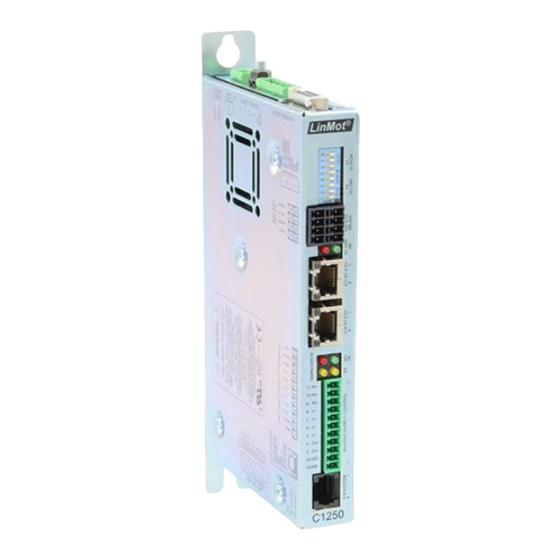
Page 7: Interfaces
Installation Guide C1250 3 Interfaces Figure 2: C1250-xx-XC-xS-xxx NTI AG / LinMot 0185-1063-E_6V16_IG_Drives_C1250 Page 7 of 32... -
Page 8: Functionality
● ● ● ● ● ● ● ● ● ● ● ● ● ● ● ● ● Controllable Motors LinMot P01…(Motor Link P) ● ● ● ● ● ● ● ● ● ● ● ● ● ● ● ● ●... -
Page 9: Software
Installation Guide C1250 5 Software The configuration software LinMot-Talk is free of charge and can be downloaded from the LinMot homepage. 6 Power Supply and Grounding In order to assure a safe and error free operation, and to avoid severe damage to system components, all system components must be well grounded to protective earth PE. -
Page 10: Calibrated Measuring Amplifier (C1250-Xx-Xc-Xs-Cxx)
If motor supply voltage exceeds 90 VDC, the drive will go into error state. • Use 60/75 °C copper conductors only • Conductor Cross-Section 2.5 mm (AWG14) max Length 3 m Page 10 of 32 0185-1063-E_6V16_IG_Drives_C1250 NTI AG / LinMot... -
Page 11: X2/X3 Motor Connection
Use Y-style motor cables only (for example K15-Y/C)! A W-style cable has a different shielding, so it cannot be modified to a Y-style cable! • The motor cable length must not exceed 30 m. NTI AG / LinMot 0185-1063-E_6V16_IG_Drives_C1250 Page 11 of 32... -
Page 12: X13
Digital outputs (X4.3 & X4.4): 24 VDC / max. 500 mA, peak 1.4 A (will shut down if exceeded) be ordered X4.3: Can be used as brake output for LinMot motors separately: see chapter 15 Analog inputs: 12 bit A/D converted until V1RH3: X4.9:... -
Page 13: X17 - X18
Setting the ID high & low to 0xFF resets the drive to manufacturer settings! The use of these switches depends on the type of fieldbus which is used. Please see the corresponding manual for further information. NTI AG / LinMot 0185-1063-E_6V16_IG_Drives_C1250 Page 13 of 32... -
Page 14: Leds
RT Bus State Display Signal: Color: Description: Green RT BUS ERROR Error The use of these LEDs depends on the type of fieldbus which is used. Please see the corresponding manual for further information Page 14 of 32 0185-1063-E_6V16_IG_Drives_C1250 NTI AG / LinMot... -
Page 15: Led Blink Codes
If also both RT LEDs are on, the drive is in the bootstrap mode. Set S5 to off. The meaning of the error codes can be found in the Usermanual_MotionCtrl_Software_SG5-SG7 and the user manual of the installed interface software. These documents are provided together with LinMot-Talk configuration software and can be downloaded from www.linmot.com. -
Page 16: Safety Wiring
= 3 Performance Level PL = d Diagnostic Coverage DC = high (99%) Mean Time to hazardous failure of one channel MTTF = high (100 years typically, see calculation example below) Page 16 of 32 0185-1063-E_6V16_IG_Drives_C1250 NTI AG / LinMot... - Page 17 (24 h/day * 365.25 days/year * 3600 s/h) / 20 s = 1'577'880 operations per year MTTF / (0.1 * n ) = 126.75 years (This has to be limited to 100 years according the standard for further calculations) high (100 years) NTI AG / LinMot 0185-1063-E_6V16_IG_Drives_C1250 Page 17 of 32...
-
Page 18: Physical Dimension
Installation Guide C1250 11 Physical Dimension C1250 Series single axis drive C1250-xx-XC-0S C1250-xx-XC-1S Width mm (in) 25.3 (1.0) Height mm (in) 166 (6.54) 176 (6.93) Height with fixings mm (in) 206 (8.11) 216 (8.50) Depth mm (in) 106 (4.2) Weight g (lb) 630 (1.4) -
Page 19: Power Supply Requirements
If the power supply rises too high when breaking, connect an additional capacitor to the motor power supply. It is recommended to use a capacitor >= 10’000 μF (install capacitor close to the drive supply!). NTI AG / LinMot 0185-1063-E_6V16_IG_Drives_C1250... -
Page 20: Safety Notes For The Installation According Ul
Motor overload protection must be provided externally in the end-use. Motor Overload protection can alternatively be provided when the connected motor has a thermal sensor rated 5V DC, max. 100 mA which is connected to the drive thermal sensor input (X3). (The LinMot P01-Motors are therefore protected by the drive) •... -
Page 21: Ordering Information
POWERLINK Drive (72V/25A/STO), Calibrated Measuring Amplifier 0150-4139 C1250-SC-XC-1S-C00 SERCOS III Drive (72V/25A/STO), Calibrated Measuring Amplifier 0150-4143 C1250-CM-XC-1S-C00 CIP Sync Drive (72V/25A/STO), Calibrated Measuring Amplifier 0150-4122 C1250-CC-XC-1S-C00 CC Link Drive (72V/25A/STO), Calibrated Measuring Amplifier 0150-4147 NTI AG / LinMot 0185-1063-E_6V16_IG_Drives_C1250 Page 21 of 32... - Page 22 T-Supply 420 VA, 1x208/220/230/240 VAC 0150-1859 Bold items are strongly recommended accessories! The connectors have to be ordered separately and are not included with the drive! Use isolated USB RS232 converter for configuration! Page 22 of 32 0185-1063-E_6V16_IG_Drives_C1250 NTI AG / LinMot...
-
Page 23: International Certifications
Canada and eases certification of your machines and systems in these areas. File number E316095 UL 508C Power Conversion Equipment CSA C22.2 Industrial Control Equipment Available from Hardware Version 1, Revision H2 NTI AG / LinMot 0185-1063-E_6V16_IG_Drives_C1250 Page 23 of 32... - Page 24 Installation Guide C1250 Page 24 of 32 0185-1063-E_6V16_IG_Drives_C1250 NTI AG / LinMot...
- Page 25 Installation Guide C1250 NTI AG / LinMot 0185-1063-E_6V16_IG_Drives_C1250 Page 25 of 32...
- Page 26 Installation Guide C1250 Page 26 of 32 0185-1063-E_6V16_IG_Drives_C1250 NTI AG / LinMot...
- Page 27 Installation Guide C1250 NTI AG / LinMot 0185-1063-E_6V16_IG_Drives_C1250 Page 27 of 32...
- Page 28 Installation Guide C1250 Page 28 of 32 0185-1063-E_6V16_IG_Drives_C1250 NTI AG / LinMot...
- Page 29 Installation Guide C1250 NTI AG / LinMot 0185-1063-E_6V16_IG_Drives_C1250 Page 29 of 32...
- Page 30 Installation Guide C1250 Page 30 of 32 0185-1063-E_6V16_IG_Drives_C1250 NTI AG / LinMot...
-
Page 31: Declaration Of Conformity Ce-Marking
Installation Guide C1250 17 Declaration of Conformity CE -Marking NTI AG / LinMot ® Bodenaeckerstrasse 2 8957 Spreitenbach Switzerland Tel.: +41 (0)56 419 91 91 Fax: +41 (0)56 419 91 92 declares under sole responsibility the compliance of the products: •... -
Page 32: Contact & Support
LinMot USA Inc. N1922 State Road 120, Unit 1 Lake Geneva, WI 53147 Phone 262-743-2555 E-Mail: usasales@linmot.com Web: http://www.linmot-usa.com/ Please visit http://www.linmot.com/contact to find the distribution close to you. Smart solutions are… Page 32 of 32 0185-1063-E_6V16_IG_Drives_C1250 NTI AG / LinMot...
Need help?
Do you have a question about the C1250 Series and is the answer not in the manual?
Questions and answers