
Related Manuals for LinMot C1200


Summary of Contents for LinMot C1200
- Page 1 C1200 Servo Drives Installation Guide Please visit http://www.linmot.com to check for the latest version of this document! July 2016 Doc. Nr. 0185-1063-E_6V6_IG_Drives_C1250...
- Page 2 NTI AG reserves itself the right to make changes at any time and without notice to reflect further technical advance or product improvement. NTI AG Tel.: +41 (0)56 419 91 91 ® LinMot Fax: +41 (0)56 419 91 92 Bodenaeckerstrasse 2 Email: office@LinMot.com...
- Page 3 CH-8957 Spreitenbach Homepage: www.LinMot.com July 2016 Doc. Nr. 0185-1063-E_6V6_IG_Drives_C1250...
-
Page 5: Table Of Contents
Installation Guide C1200 Table of Contents Table of Contents ..............................5 1 Important Safety Instructions ........................... 6 2 System Overview..............................8 3 Interfaces ................................9 4 Functionality ..............................10 5 Software ................................10 6 Power Supply and Grounding ......................... 11 7 Description of the connectors / Interfaces .................... -
Page 6: Important Safety Instructions
The procedural notes and circuit details described in this documentation are only proposals. It is up to the user to check whether they can be transferred to the particular applications. NTI AG / LinMot does not accept any liability for the suitability of the procedures and circuit proposals described. - Page 7 Installation Guide C1200 Installation The drives must be installed and cooled according to the instructions given in the corresponding documentation. The ambient air must not exceed degree of pollution 2 according to EN 61800−5−1. Ensure proper handling and avoid excessive mechanical stress. Do not bend any components and do not change any insulation distances during transport or handling.
-
Page 8: System Overview
Installation Guide C1200 2 System Overview Figure 1: Typical servo system C12x0-XX: Servo drive, motor and power supply Page 8 of 31 NTI AG / LinMot... -
Page 9: Interfaces
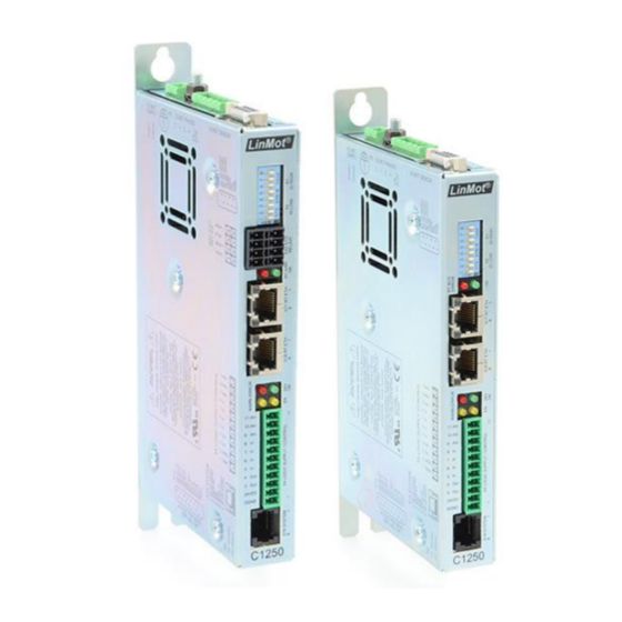
Installation Guide C1200 3 Interfaces Figure 2: C1250-xx-XC-xS-xxx NTI AG / LinMot Page 9 of 31... -
Page 10: Functionality
● ● ● ● ● ● ● ● ● STO (2 Safety Relays) 5 Softw are The configuration software LinMot-Talk is free of charge and can be downloaded from the LinMot homepage. Page 10 of 31 NTI AG / LinMot... -
Page 11: Power Supply And Grounding
Power supply connectors must not be connected or disconnected while DC voltage is present. Do not disconnect system components until all LinMot drive LEDs have turned off. (Capacitors in the power supply may not fully discharge for several minutes after input voltage has been disconnected). -
Page 12: Description Of The Connectors / Interfaces
Installation Guide C1200 7 Description of the connectors / Interfaces 7.1 PE Protective Earth Use min. 4mm (AWG11) Tightening torque: 2Nm (18 lbin) 7.2 X1 Motor Supply PGND Motor Supply: 72VDC nominal, 24...85VDC Connector has to be ordered Absolute max. - Page 13 Installation Guide C1200 7.4 X3 Motor Sensor / Brake LinMot Motor: EC Motor: Do not connect Do not connect Brake+ Brake+ Do not connect Do not connect Do not connect +5VDC +5VDC AGND AGND Sensor Sine Sensor Sine / Hall Switch U...
-
Page 14: X13
Installation Guide C1200 7.5 X4 Logic Supply / IO Connection AnIn- X4.11 Configurable differential analog Input (with X4.10) AnIn+ X4.10 Configurable differential analog Input (with X4.11) AnIn X4.9 Configurable single ended analog Input X4.8 Configurable digital Input X4.7 Configurable digital Input X4.6... -
Page 15: X17 - X18
Installation Guide C1200 7.7 X17 – X18 X17 – X18 RealTime Ethernet 10/100 Mbit/s X17 RT ETH In Specification depends on RT Bus. Please refer to according documentation. X18 RT ETH Out RJ-45 7.8 X19 System (Do not connect) (Do not connect) -
Page 16: Leds
Installation Guide C1200 7.11 S5 Bootstrap Bootstrap (Internal use only) 7.12 LEDs LEDs State Displays Green 24V Logic Supply OK Yellow Motor Enabled / Error Code Low Nibble Yellow Warning / Error Code High Nibble Error 7.13 RT Bus LEDs... -
Page 17: Led Blink Codes
Also see in the Usermanual_LinMot-Talk under chapter trouble shooting. The meaning of the error codes can be found in the Usermanual_MotionCtrl_Software_SG5-SG7 and the user manual of the installed interface software. These documents are provided together with LinMot-Talk configuration software and can be downloaded from www.linmot.com. -
Page 18: Safety Wiring
Installation Guide C1200 9 Safety Wiring The C1250 drives with the -1S option have internal safety functions: Two Safety relays Ksr in series, which support the supply voltage for the motor drivers. There are also two feedback contacts for each relay. - Page 19 Installation Guide C1200 DC (Diagnostic Coverage) is high (99%) assuming that the state of the feedback contacts is checked after each change of the state of the control contacts. The MTTF mainly depends on the number of operations of the safety relays.
-
Page 20: Physical Dimension
Installation Guide C1200 10 Physical Dimension C1250 Series single axis drive C12xx-xx-XC-0S C12xx-xx-XC-1S Width mm (in) 25.3 (1.0) Height mm (in) 166 (6.54) 176 (6.93) Height with fixings mm (in) 176 (6.93) 216 (8.5) Depth mm (in) 106 (4.2) Weight g (lb) 630 (1.4) -
Page 21: Power Supply Requirements
Installation Guide C1200 11 Pow er Supply Requirement s 11.1 Motor Power Supply The calculation of the needed power for the Motor supply is depending on the application and the used motor. The nominal supply voltage is 72VDC. The possible range is from 24 to 85VDC. -
Page 22: Safety Notes For The Installation According Ul
Motor overload protection must be provided externally in the end-use. Motor Overload protection can alternatively be provided when the connected motor has a thermal sensor rated 5V DC, max. 100mA which is connected to the drive thermal sensor input (X3). (The LinMot P01-Motors are therefore protected by the drive) ... -
Page 23: Ordering Information
Installation Guide C1200 14 Ordering Information Drive Description Art. No. C1250-PN-XC-0S-000 PROFINET Drive (72V/25A) 0150-1888 C1250-PD-XC-0S-000 PROFINET Profidrive Drive (72V/25A) 0150-2618 C1250-IP-XC-0S-000 ETHERNET IP Drive (72V/25A) 0150-1886 C1250-LU-XC-0S-000 ETHERNET LinUDP Drive (72V/25A) 0150-2491 C1250-EC-XC-0S-000 ETHERCAT Drive (72V/25A) 0150-1884 C1250-DS-XC-0S-000 ETHERCAT CiA402 Drive (72V/25A) -
Page 24: International Certifications
Installation Guide C1200 15 International Certifications Certifications Europe See chapter 16 Declaration of Conformity CE-Marking Ref. Certif. No. CH-7685 IECEE CB SCHEME USA / Canada All products marked with this symbol are tested and recognized by Underwriters Laboratories and the production facilities are checked quarterly by an UL inspector. - Page 25 Installation Guide C1200 NTI AG / LinMot Page 25 of 31...
- Page 26 Installation Guide C1200 Page 26 of 31 NTI AG / LinMot...
- Page 27 Installation Guide C1200 NTI AG / LinMot Page 27 of 31...
- Page 28 Installation Guide C1200 Page 28 of 31 NTI AG / LinMot...
- Page 29 Installation Guide C1200 NTI AG / LinMot Page 29 of 31...
-
Page 30: Declaration Of Conformity Ce-Marking
Installation Guide C1200 16 Declaration of Conformity CE -Marking NTI AG / LinMot ® Bodenaeckerstrasse 2 8957 Spreitenbach Switzerland Tel.: +41 (0)56 419 91 91 Fax: +41 (0)56 419 91 92 declares under sole responsibility the compliance of the products: ... -
Page 31: Contact & Support
Installation Guide C1200 Contact & Support SCHWEIZ NTI AG Bodenaeckerstr. 2 CH-8957 Spreitenbach Sales and Administration: +41-(0)56-419 91 91 office@linmot.com Tech. Support: +41-(0)56-544 71 00 support@linmot.com http://www.linmot.com/support Tech. Support (Skype): skype:support.linmot Fax: +41-(0)56-419 91 92 Web: http://www.linmot.com/ LinMot USA Inc.
Need help?
Do you have a question about the C1200 and is the answer not in the manual?
Questions and answers