Table of Contents
Advertisement
Quick Links
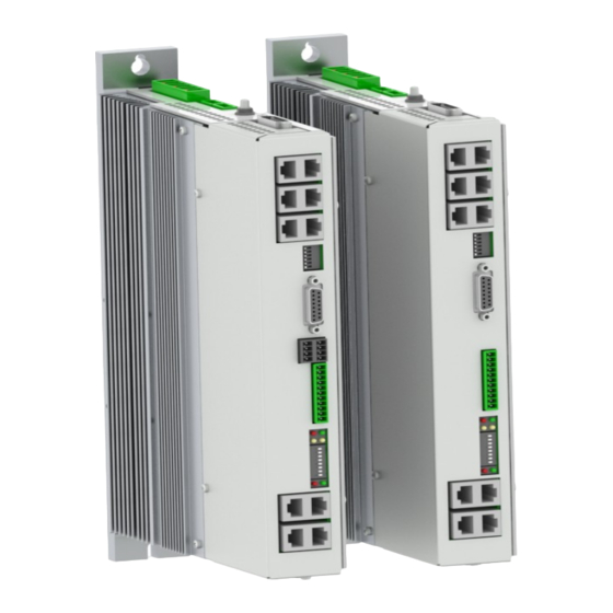
E14x0 V1 Rev. E and Rev. F Servo Drives
Eine Deutsche Version kann unter http://www.linmot.com bezogen werden!
Please visit http://www.linmot.com to check for the latest version of this document!
ATTENTION: The connectors have to be ordered separately and are
DC01-E1400/X4/X30
DC01-E1400/X4/X30/X33
Installation Guide
This document applies to the following drives:
E1400-GP-QN-xS
E1450-PL-QN-xS
E1450-SE-QN-xS
E1450-IP-QN-xS
not included with the drive!
Drive Connector Set for E1400-0S
Drive Connector Set for E1400-1S
E1430-DP-QN-xS
E1450-EC-QN-xS
E1450-PN-QN-xS
E1450-SC-QN-xS
0150-3452
0150-3453
Advertisement
Table of Contents

Related Manuals for LinMot E14 0 V1 Series


Summary of Contents for LinMot E14 0 V1 Series
- Page 1 E14x0 V1 Rev. E and Rev. F Servo Drives Installation Guide Eine Deutsche Version kann unter http://www.linmot.com bezogen werden! Please visit http://www.linmot.com to check for the latest version of this document! This document applies to the following drives: E1400-GP-QN-xS E1430-DP-QN-xS...
- Page 2 NTI AG. LinMot® is a registered trademark of NTI AG. The information in this documentation reflects the stage of development at the time of press and is therefore without obligation.
-
Page 3: Table Of Contents
7 Error Codes........................17 8 Safety Wiring.........................18 9 Physical Dimensions....................19 10 Power Supply Requirements..................20 11 Regeneration of Power / Regeneration Resistor.............20 12 Ordering Information....................21 13 International Certifications..................21 14 Declaration of Conformity CE-Marking..............22 15 Contact Addresses.....................23 NTI AG / LinMot ® www.LinMot.com Page 3/23... -
Page 4: Important Safety Instructions
The procedural notes and circuit details described in this documentation are only proposals. It is up to the user to check whether they can be transferred to the particular applications. NTI AG / LinMot does not accept any liability for the suitability of the procedures and circuit proposals described. - Page 5 PE connection is required. • The heat sink of the drive has an operating temperature of > 80 °C: Contact with the heat sink results in burns. NTI AG / LinMot ® www.LinMot.com Page 5/23...
-
Page 6: System Overview
E1400 V1 Rev. E Installation Guide 2 System Overview Typical Servo System E14x0-XX: Servo Drive, Motor and Power Supply. ® Page 6/23 www.LinMot.com NTI AG / LinMot... -
Page 7: Functionality And Interfaces
● ● ● ● ● ● ● ● ● ● ● ● ● ● rms continuous Controllable Motors LinMot P10-70x…(Motor Link C) ● ● ● ● ● ● ● ● ● ● ● ● ● ● Selected motors (contact support) ●... -
Page 8: Power Supply And Grounding
In order to assure a safe and error free operation, and to avoid severe damage to system components, all system components must be well grounded to protective earth PE. This includes both LinMot and all other control system components on the same ground bus. -
Page 9: Description Of The Connectors / Interfaces
- Use a cross-head screw driver (PH1) - Use 60/75°C copper conductors only - Conductor cross-section: 2.5 – 4 mm (depends on Motor current) / AWG 24 -12 - Stripping length 10mm NTI AG / LinMot ® www.LinMot.com Page 9/23... -
Page 10: X2-V1 Rev. D/E
Use an EMC shield clamp for fixing. Attention: KTY+ and KTY- are not referenced to ground! They are on DC- voltage! An isolated thermistor is necessary! Especially LinMot D01 and D02 Motors can not be connected! Screw Terminals: - Tightening torque: 0.7 - 0.8 Nm (6.2 –... -
Page 11: X3-V2
- Stripping length: 10mm - Internal Fuse (F2): 3AT (slow blow, Schurter OMT125, 3404.0118.xx, UL File Number: E41599) CAUTION: For continued protection against risk of fire, replace only with same type and rating of fuse. NTI AG / LinMot ® www.LinMot.com... -
Page 12: X33
X7 is internally connected to X8 (1:1 connection) 6.10 PROFIBUS DP (only available on E1430-DP-QN) Not connected (isolated) Not connected Not connected RxD/TxD-P RxD/TxD-N CNTR-P Not connected (isolated) case Shield DSUB-9 (f) Max. Baud rate: 12Mbaud ® Page 12/23 www.LinMot.com NTI AG / LinMot... -
Page 13: X10 - X11
Max Output Frequency: 4 M counts/s with quadrature decoding, 250ns edge separation Differential Hall Switch Inputs (RS422): Input Frequency: <1kHz Enc. Alarm In: 5V / 1mA Sensor Supply: 5VDC max. 100mA / 9VDC 100mA (SW selectable) NTI AG / LinMot ® www.LinMot.com Page 13/23... -
Page 14: X15 - X16
RJ-45 6.15 System Do not connect Do not connect RS232 Rx RS232 Tx Do not connect Do not connect case Shield RJ-45 Use isolated USB-RS232 converter (Art.-No. 0150-2473) for configuration over RS232. ® Page 14/23 www.LinMot.com NTI AG / LinMot... -
Page 15: X20
Switch 2: Termination resistor for RS485 on CMD (120R between pin 1 and 2 on X7/X8) on/off Switch 1: AnIn2 pull down (4k7 Pull down on X4.4). Set to ON, if X4.4 is used as digital output. Factory setting: all switches “on” except S5.5 (Bootstrap) and S5.6 (Override to DHCP) NTI AG / LinMot ® www.LinMot.com... -
Page 16: Leds
Bus ID Low (0 … F). Bit 1 is the LSB, bit 4 the MSB. The use of these switches depends on the type of fieldbus which is used. Please see the corresponding manual for further information. ® Page 16/23 www.LinMot.com NTI AG / LinMot... -
Page 17: Error Codes
The meaning of the error codes can be found in the Usermanual_MotionCtrl_Software_SG5 and the user manual of the installed interface software. These documents are provided together with LinMot-Talk configuration software and can be downloaded from www.linmot.com. NTI AG / LinMot ®... -
Page 18: Safety Wiring
Drive Classification according EN ISO 13849-1 (safety of machinery) Category cat = 3 Performance Level PL = d Diagnostic Coverage DC = high Mean Time to hazardous failure of one channel MTTFd = high ® Page 18/23 www.LinMot.com NTI AG / LinMot... -
Page 19: Physical Dimensions
≥ 200 (8) top / bottom Distance between drives (cold plate mm (in) ≥ 0 (0) left/right cooling) ≥ 200 (8) top / bottom 1 Drive can be mounted upside down (motor connector on bottom side) NTI AG / LinMot ® www.LinMot.com Page 19/23... -
Page 20: Power Supply Requirements
Use a circuit breaker C16 and conductor cross section of 2.5mm for mains connections! The LinMot line filter NF01-FN258-16-07 must be connected near the supply connector of the drive to conform to the EMC requirements of CE. Current consumption: Startup Current: Soft start over 50 Ohm charge resistor. -
Page 21: Ordering Information
ATTENTION: The connectors have to be ordered separately and are not included with the drive! Use isolated USB RS232 converter for configuration! 13 International Certifications Certifications Europe See chapter “14 Declaration of Conformity CE-Marking“ UL508C pending NTI AG / LinMot ® www.LinMot.com Page 21/23... -
Page 22: Declaration Of Conformity Ce-Marking
E1400 V1 Rev. E Installation Guide 14 Declaration of Conformity CE-Marking Manufacturer: NTI AG / LinMot ® Haerdlistrasse 15 8957 Spreitenbach Switzerland Tel.: +41 (0)56 419 91 91 Fax: +41 (0)56 419 91 92 ® Products: LinMot drives Type Art.-No. -
Page 23: Contact Addresses
LinMot USA Inc. N1922 State Road 120, Unit 1 Lake Geneva, WI 53147 Phoone: 262-743-2555 E-Mail: usasales@linmot.com Web: http://www.linmotusa.com/ Please visit http://www.linmot.com/ to find the distributor closest to you. Smart solutions are… NTI AG / LinMot ® www.LinMot.com Page 23/23...
Need help?
Do you have a question about the E14 0 V1 Series and is the answer not in the manual?
Questions and answers