Table of Contents

Subscribe to Our Youtube Channel
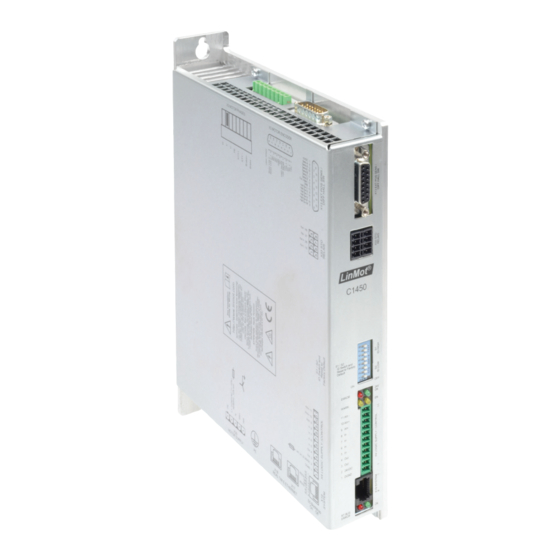
Summary of Contents for LinMot C1400
- Page 1 C1400 Servo Drives Installation Guide Eine Deutsche Version kann unter http://www.linmot.com bezogen werden! Please visit http://www.linmot.com to check for the latest version of this document! 0185-1107-E_6V4_IG_C1400 / July 2016...
- Page 2 NTI AG. LinMot® is a registered trademark of NTI AG. The information in this documentation reflects the stage of development at the time of press and is therefore without obligation.
-
Page 3: Table Of Contents
C1400 Installation Guide Table of Content 1 Important Safety Instructions..................4 2 System Overview......................6 3 Functionality and Interfaces...................7 4 Power Supply and Grounding..................8 5 Description of the connectors / Interfaces..............9 5.1 PE..........................9 5.2 X30..........................9 5.3 X2..........................10 5.4 X3..........................10 5.5 X4 ..........................11 5.6 X13..........................11... -
Page 4: Important Safety Instructions
• It is up to the user to check whether they can be transferred to the particular applications. NTI AG / LinMot does not accept any liability for the suitability of the procedures and circuit proposals described. LinMot servo drives and the accessory components can include live and moving parts (depending on •... - Page 5 C1400 Installation Guide Installation The drives must be installed and cooled according to the instructions given in the corresponding • documentation. The ambient air must not exceed degree of pollution 2 according to EN 61800−5−1. • Ensure proper handling and avoid excessive mechanical stress. Do not bend any components and •...
-
Page 6: System Overview
C1400 Installation Guide preliminary 2 System Overview Typical Servo System C14x0-XX: Servo Drive, Motor and Power Supply. Page 6/21 www.LinMot.com NTI AG / LinMot ®... -
Page 7: Functionality And Interfaces
C1400 Installation Guide 3 Functionality and Interfaces Supply Voltage Motor Supply 1x240 VAC ● ● ● ● ● ● ● ● ● ● Logic Supply 24VDC (22...26VDC) ● ● ● ● ● ● ● ● ● ● Motor Phase Current (preliminary) -
Page 8: Power Supply And Grounding
In order to assure a safe and error free operation, and to avoid severe damage to system components, all system components must be well grounded to protective earth PE. This includes both LinMot and all other control system components on the same ground bus. -
Page 9: Description Of The Connectors / Interfaces
- Use 60/75°C copper conductors only - Conductor cross-section: 2.5mm (AWG 12) - Stripping length 7mm LinMot Article Number: 0150-3607 (DC01-C1400/X30) Operating of the drive is only allowed with the above article! No other type of connector shall be used! NTI AG / LinMot ®... - Page 10 The Shield of the motor cable has to be mounted with a surface as large as possible (low ohm, low impedance). Use an EMC shield clamp for fixing. Attention: An isolated thermistor is necessary! Especially LinMot D01 and D02 Motors can not be connected! Screw Terminals: - Spring-cage connector - Use 60/75°C copper conductors only...
-
Page 11: X13
- Stripping length: 10mm - The 24VDC supply for the control circuit (X4.2) must be protected with an external fuse (3A slow blow) LinMot Article Number: 0150-3447 (DC01-Signal/X4) Operating of the drive is only allowed with the above article! No other type of connector shall be used! 5.6 X13... -
Page 12: X17 - X18
C1400 Installation Guide preliminary 5.7 X17 - X18 X17 - X18 RealTime Ethernet 10/100 Mbit/s (not available on -CI Drives) X18 RT ETH Out Specification depends on RT-Bus Type. Please refer to according documentation. X17 RT ETH In RJ-45 5.8 X7 - X8... -
Page 13: Leds
C1400 Installation Guide 5.10 LEDs LEDs State Display Green 24V Logic Supply OK Yellow Motor Enabled / Error Code Low Nibble Yellow Warning / Error Code High Nibble Error 5.11 RT BUS LEDs RT Bus LEDs RT Bus State Display... -
Page 14: Error Codes
The meaning of the error codes can be found in the “0185-1093- E_6V5_MA_MotionCtrlSW-SG5-SG7.pdf” and the user manual of the installed interface software. These documents are provided together with LinMot-Talk configuration software and can be downloaded from www.linmot.com. Page 14/21 www.LinMot.com... -
Page 15: Physical Dimensions
C1400 Installation Guide 7 Physical Dimensions NTI AG / LinMot ® www.LinMot.com Page 15/21... - Page 16 C1400 Installation Guide preliminary C1400 Series C1400-CI- C14X0-XX- C14X0-XX- single axis drive VS-0S XX-0S XX-1S Width mm (in) 35 (1.38) 43.5 (1.71) Height mm (in) 200 (7.87) 235 (9.25) Depth mm (in) 153 (6.02) 193 (7.60) Weight kg (lb) Mounting...
-
Page 17: Power Supply Requirements
Use a circuit breaker C16 and conductor cross section of 2.5mm for mains connections! The LinMot line filter XXXX must be connected near the supply connector of the drive to conform to the EMC requirements of CE. Signal Power Supply The logic supply needs a regulated power supply of a nominal voltage of 24 VDC. -
Page 18: Ordering Information
0150-2637 Accessories Description Art. No. Isolated USB-RS232 converter Isolated USB RS232 converter with config. cable 0150-2473 RR01-68/100 Regeneration resistor (68R, 100W, 1000V) for C1400 0150-3581 NF01-FS34984-6-61 1-phase line filter for C1400 0150-2747 DC01-C1400/X4/X30 Drive Connector Set for C1400-0S 0150-3676 DC01-C1400/X4/X30/X33... - Page 19 C1400 Installation Guide NTI AG / LinMot ® www.LinMot.com Page 19/21...
-
Page 20: Ec Declaration Of Conformity Ce-Marking
C1400 Installation Guide preliminary 12 EC Declaration of Conformity CE-Marking ® NTI AG / LinMot Bodenaeckerstrasse 2 8957 Spreitenbach Switzerland Tel.: +41 (0)56 419 91 91 Fax: +41 (0)56 419 91 92 declares under sole responsibility the compliance of the products:... -
Page 21: Contact Addresses
Elkhorn, WI 53121 Sales and Administration: 877-546-3270 262-743-2555 Tech. Support: 877-804-0718 262-743-1284 Fax: 800-463-8708 262-723-6688 E-Mail: usasales@linmot.com Web: http://www.linmotusa.com/ Please visit http://www.linmot.com/ to find the distributor closest to you. Smart solutions are… NTI AG / LinMot ® www.LinMot.com Page 21/21...


Need help?
Do you have a question about the C1400 and is the answer not in the manual?
Questions and answers