Table of Contents

Related Manuals for LinMot E1450-PL-QN-0S


Summary of Contents for LinMot E1450-PL-QN-0S
- Page 1 E14x0 V2 Servo Drives Installation Guide Für eine Deutsche Version bitte den Support kontaktieren! Please visit http://www.linmot.com to check for the latest version of this document! 0185-1101-E_6V4_IG_E1400V2.odt / 11. Apr. 2016...
- Page 2 NTI AG. LinMot® is a registered trademark of NTI AG. The information in this documentation reflects the stage of development at the time of press and is therefore without obligation.
-
Page 3: Table Of Contents
LEDs.............................17 RT BUS LEDs........................17 S1 - S2..........................17 Error Codes..........................18 Safety Wiring........................19 Physical Dimensions......................21 Power Supply Requirements....................22 Regeneration of Power / Regeneration Resistor..............22 Ordering Information......................23 International Certifications....................23 Declaration of Conformity CE-Marking................26 Contact Addresses.......................27 NTI AG / LinMot ® www.LinMot.com Page 3/27... -
Page 4: Important Safety Instructions
The procedural notes and circuit details described in this documentation are only • proposals. It is up to the user to check whether they can be transferred to the particular applications. NTI AG / LinMot does not accept any liability for the suitability of the procedures and circuit proposals described. •... - Page 5 PE connection is required. The heat sink of the drive has an operating temperature of > 80 °C: Contact • with the heat sink results in burns. NTI AG / LinMot ® www.LinMot.com Page 5/27...
-
Page 6: System Overview
E1400 V2 Installation Guide System Overview Typical Servo System E14x0-XX: Servo Drive, Motor and Power Supply. Page 6/27 www.LinMot.com NTI AG / LinMot ®... -
Page 7: Functionality And Interfaces
● ● ● ● ● ● ● ● ● ● ● ● ● ● ● rms continuous Controllable Motors LinMot P10-70x…(Motor Link C) ● ● ● ● ● ● ● ● ● ● ● ● ● ● ● ● ●... -
Page 8: Differences Between V1 Rev. E/F And V2
Attention: Configuration can not be directly imported from from a V1 into a V2 drive. It has to be done manually! If assistance is required contact support@linmot.com. IP Address Selection The default mode for acquiring an IP address is via DHCP. If no servers respond on the connected network, the drive switches to the IPv4 Link-Local addressing scheme (also known as APIPA on Windows systems). -
Page 9: Power Supply And Grounding
In order to assure a safe and error free operation, and to avoid severe damage to system components, all system components must be well grounded to protective earth PE. This includes both LinMot and all other control system components on the same ground bus. -
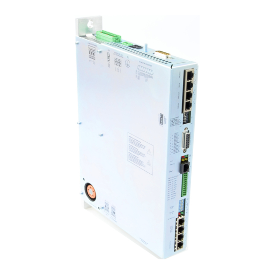
Page 10: Description Of The Connectors / Interfaces
- Use a cross-head screw driver (PH1) - Use 60/75°C copper conductors only - Conductor cross-section: 2.5 – 4 mm 2 (depends on Motor current) / AWG 24 -12 - Stripping length 10mm Page 10/27 www.LinMot.com NTI AG / LinMot ®... -
Page 11: X32
The Shield of the motor cable has to be mounted with a surface as large as possible (low ohm, low impedance). Use an EMC shield clamp for fixing (LinMot MC10-EMV/14-D Art. Nr. 0150-3631) Attention: An isolated thermistor is necessary! Especially LinMot D01 and D02... - Page 12 - Use 60/75°C copper conductors only - Conductor cross-section max. 1.5mm 2 - Stripping length: 10mm - The 24VDC supply for the control circuit (X4.2) must be protected with an external fuse (3A slow blow) Page 12/27 www.LinMot.com NTI AG / LinMot ®...
-
Page 13: X33
X7 is internally connected to X8 (1:1 connection) 7.10 X9 PROFIBUS DP (only available on E1430-DP-QN) Not connected (isolated) Not connected Not connected RxD/TxD-P RxD/TxD-N CNTR-P Not connected (isolated) case Shield DSUB-9 (f) Max. Baud rate: 12Mbaud NTI AG / LinMot ® www.LinMot.com Page 13/27... -
Page 14: X10 - X11
Max Output Frequency: 4 M counts/s with quadrature decoding, 250ns edge separation Differential Hall Switch Inputs (RS422): Input Frequency: <1kHz Enc. Alarm In: 5V / 1mA Sensor Supply: 5VDC max. 100mA / 9VDC 100mA (SW selectable) Page 14/27 www.LinMot.com NTI AG / LinMot ®... -
Page 15: X15 - X16
Internal 2-Port 10BASE-T and 100BASE-TX Ethernet Switch with Auto MDIX. RJ-45 7.14 X17 - X18 X17 - X18 RealTime Ethernet 10/100 Mbit/s X18 RT ETH Out Specification depends on RT-Bus Type. Please refer to according documentation. X17 RT ETH In RJ-45 NTI AG / LinMot ® www.LinMot.com Page 15/27... -
Page 16: X19
Switch 1: AnIn2 pull down (4k7 Pull down on X4.4). Set to ON, if X4.4 is used as digital output. Factory setting: all switches “on” except S5.5 (Bootstrap) and S5.6 (Override to DHCP) Page 16/27 www.LinMot.com NTI AG / LinMot ®... -
Page 17: Leds
Bus ID Low (0 … F). Bit 1 is the LSB, bit 4 the MSB. The use of these switches depends on the type of fieldbus which is used. Please see the corresponding manual for further information. NTI AG / LinMot ® www.LinMot.com... -
Page 18: Error Codes
The meaning of the error codes can be found in the Usermanual_MotionCtrl_Software_SG5 and the user manual of the installed interface software. These documents are provided together with LinMot-Talk configuration software and can be downloaded from www.linmot.com. Page 18/27 www.LinMot.com... -
Page 19: Safety Wiring
Category cat = 3 Performance Level PL = d Diagnostic Coverage DC = high Mean Time to hazardous failure of one channel MTTFd = high (100 years typically, see calculation example below) NTI AG / LinMot ® www.LinMot.com Page 19/27... - Page 20 = (24h/day*365.25days/year*3600s/h) / 20s = 1'577'880 operations per year MTTF / (0.1 x n ) = 126.75 years (this has to be limited to 100years according the standard for further calculations) = high (100 years) Page 20/27 www.LinMot.com NTI AG / LinMot ®...
-
Page 21: Physical Dimensions
≥ 15 (0.6) left and right (fan cooling is integrated on V2 ≥ 200 (8) top / bottom Drives) Distance between drives (cold plate mm (in) ≥ 0 (0) left/right cooling) ≥ 200 (8) top / bottom NTI AG / LinMot ® www.LinMot.com Page 21/27... -
Page 22: Power Supply Requirements
Use a circuit breaker C16 and conductor cross section of 2.5mm • mains connections! The LinMot line filter NF01-FS34985-20-71 (0150-2746) must be • connected as near as possible to the supply connector of the drive to conform to the EMC requirements of CE. Maximum Distance between Drive and Filter is 0.15m. -
Page 23: Ordering Information
ATTENTION: The connectors have to be ordered separately and are not included with the drive! Use isolated USB RS232 converter for configuration! 14 International Certifications Certifications Europe See chapter “15 Declaration of Conformity CE-Marking“ UL508C pending NTI AG / LinMot ® www.LinMot.com Page 23/27... - Page 24 E1400 V2 Installation Guide Page 24/27 www.LinMot.com NTI AG / LinMot ®...
- Page 25 E1400 V2 Installation Guide NTI AG / LinMot ® www.LinMot.com Page 25/27...
-
Page 26: Declaration Of Conformity Ce-Marking
E1400 V2 Installation Guide 15 Declaration of Conformity CE-Marking NTI AG / LinMot ® Bodenaeckerstrasse 2 8957 Spreitenbach Switzerland Tel.: +41 (0)56 419 91 91 Fax: +41 (0)56 419 91 92 declares under sole responsibility the compliance of the products:... -
Page 27: Contact Addresses
Elkhorn, WI 53121 Sales and Administration: 877-546-3270 262-743-2555 Tech. Support: 877-804-0718 262-743-1284 Fax: 800-463-8708 262-723-6688 E-Mail: usasales@linmot.com Web: http://www.linmotusa.com/ Please visit http://www.linmot.com/ to find the distributor closest to you. Smart solutions are… NTI AG / LinMot ® www.LinMot.com Page 27/27...
Need help?
Do you have a question about the E1450-PL-QN-0S and is the answer not in the manual?
Questions and answers