Table of Contents
Advertisement
Quick Links
Advertisement
Table of Contents

Related Manuals for Baicells Nova-233 G2


Summary of Contents for Baicells Nova-233 G2
- Page 1 Nova-233 G2 Outdoor 2x1W TDD eNodeB Installation Guide December 2019 Version 1.13...
- Page 2 Disclaimer The information in this document is subject to change at any time without notice. For more information, please consult with a Baicells technical engineer or the support team. Refer to the “Contact Us” section below. Disposal of Electronic and Electrical Waste Pursuant to the WEEE EU Directive, electronic and electrical waste must not be disposed of with unsorted waste.
- Page 3 Support Resources Documentation - Baicells product data sheets, this document, and other technical • manuals may be found at Baicells > Resources > Documentation. BaiTips - The BaiTips, under Baicells > Resources > • BaiTips are where periodic suggestions about how to improve equipment performance are posted.
-
Page 4: Safety Information
For the safety of installation personnel and for the protection of the equipment from damage, please read all safety warnings. If you have any questions concerning the warnings, before installing or powering on the eNB contact the Baicells support team. Warning IMPORTANT SAFETY INSTRUCTIONS This warning symbol means danger. -
Page 5: Table Of Contents
Table of Contents 1 Overview ........................7 1.1 Introduction <rewrote> .................... 7 1.2 Features ........................8 2 Preparing to Install ......................9 2.1 Personnel & Network Design ..................9 2.2 Cables .......................... 9 2.3 Form Factor ........................ 10 2.4 Location & Environment .................... 11 2.5 Grounding &... - Page 6 List of Figures Figure 1-1: Nova-233 eNB......................7 Figure 1-2: LTE Network Architecture ..................8 Figure 2-1: LEDs & Interfaces ....................10 Figure 2-2: Weatherproofing ....................11 Figure 2-3: CloudCore Login ..................... 12 Figure 3-1: Installation Process Overview ................13 Figure 3-2: GPS Antenna ......................
-
Page 7: Overview
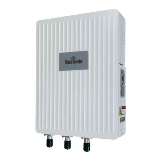
Overview 1.1 Introduction The Baicells Nova-233 Generation 2 (G2) Outdoor 2x1W eNodeB (eNB) (Figure 1-1) is a high- performing outdoor micro base station that is based on 3GPP Long-Term Evolution (LTE) Time Division Duplexing (TDD) technology. The eNB is part of an operator's broadband wireless network, and with user equipment (UE) - also called Customer Premise Equipment (CPE) - allows users to have a wireless connection to the Internet. -
Page 8: Features
Figure 1-2: LTE Network Architecture 1.2 Features Following are the key features of the Baicells Nova-233 eNB. The full technical specifications are provided in Appendix A. All product specifications are kept up to date and referred to as data sheets on the Baicells website. -
Page 9: Preparing To Install
2.1 Personnel & Network Design Installation personnel should follow standard, industry safety precautions when installing a Baicells Nova-233 eNB. Installers should refer to the operator’s network design plan for information about specific network components, RF coverage goals for the specific cell site, IP addressing, and configuration settings. -
Page 10: Form Factor
2.3 Form Factor The 1WG2 eNB has a sleek form factor: 8.9” (H) x 12” (W) x 2.9” (D) / 227mm (H) x 305mm (W) x 74mm (D), as shown in Figure 2-1. The unit weighs only 9.7 lbs (4.4 kg). The LED indicators appear on the side of the unit, and are described in Table 2-2. -
Page 11: Location & Environment
2.4 Location & Environment When determining where to place the eNB, you need to consider factors such as climate, hydrology, geology, the possibility of earthquakes, reliable electric power, and transportation access. Refer to the technical specifications in Appendix Avoid locating the eNB in areas where there may be extreme temperatures, harmful gases, unstable voltages, volatile vibrations, loud noises, flames, explosives, or electromagnetic interference (e.g., large radar stations, transformer substations). -
Page 12: Open A Cloudcore Account
Step 3: Complete the mandatory fields, and again click on Sign up. You will receive an email from Baicells. In the email, click on the CloudCore link to go to the login page. Enter your login user name (email address) and password to authenticate. You are... -
Page 13: Installation
Installation Some cell site structures may have existing frameworks for attaching the eNB and antenna. For purposes of explaining the installation procedure, this section assumes the eNB will be installed on a support pole or on a wall. 3.1 Process Overview Figure 3-1 provides an overview of the installation process. -
Page 14: Connect Cables
The Nova-233 eNB has several interfaces on the bottom and side of the unit. Refer to previous Figure 2-1 and Table 2-3. Please review the following guidelines concerning cable layout and installation. Follow all specifications provided by manufacturers of non-Baicells products used. General guidelines: RF antenna feeder cable bending radius: 7/8”... -
Page 15: Connect Gps Antenna Cable
3.3.2 Connect GPS Antenna Cable Follow the procedure below to connect the GPS antenna cable to the eNB. 1. Insert the GPS jumper cable into a cold shrink tube. 2. Connect one end of the GPS jumper cable to the GPS antenna. 3. -
Page 16: Connect Ethernet Cable
Figure 3-3: WAN Connect Type For purposes of explaining the WAN cabling, fiber optic cable is used as the example. Follow the steps below to attach the fiber optic cable to the eNB. 1. Use an M4 cross screwdriver to unscrew the three screws on the cover of the wiring cavity located on the side of the eNB (Figure 3-4). -
Page 17: Attach Power Connector
3.3.6 Attach Power Connector The two ends of the power adaptor are bare terminal ends, since the distance between the installation site and the power supply device will vary. You will need to make the power cable specific to this site, and attach the power plug and power terminal on the two ends of the power adaptor. -
Page 18: Power On The Enb To Check Leds
The initial basic configuration of the eNB covers the minimal parameters required for the eNB to connect to the backhaul and to the Baicells CloudCore. This section does not cover all configuration options available through the eNB GUI. Please refer to the document referenced above for information on all GUI menus and fields. -
Page 19: Figure 3-8: Gui Login
Go to the BTS Settings > Management Server menu (Figure 3-9). b. Enter baiomc.cloudapp.net:48080/smallcell/AcsService as the management server. c. Enter your unique CloudKey that was provided by Baicells. The CloudKey is operator-specific and enables devices, upon power up, to be added automatically to your OMC account. -
Page 20: Figure 3-10: Wan/Lan
5. Verify the core network connection between the eNB and the Mobility Management Entity (MME) in the Baicells CloudCore. Go to Network > MME/IPSec Binding (Figure 3-12). Do not change the IPSec Setting fields. They should be left with their default values. -
Page 21: Figure 3-12: Mme&Ipsec Binding
Figure 3-12: MME&IPSec Binding 6. Configure the eNB's local gateway (LGW) connection to the backhaul network. The eNB splits the data plane and control plane. The data plane is sent out the LGW path, while the control plane is routed through the IPSec tunnel to the CloudCore EPC. a. -
Page 22: Figure 3-13: Quick Setting
SSF = 5. Enter a unique Physical Cell Identifier (PCI) for this eNB, between 0 - 503. g. Make sure the Cloud EPC field is enabled in order to connect to the Baicells CloudCore. h. Enter a Cell ID for a cluster of eNBs on the same tower or other structure. The Cell ID field is equivalent to the LTE E-UTRAN Cell Identity (ECI). -
Page 23: Check Enb Status In Software
GUI or the OMC. Each method is described below. 3.6.1 eNB GUI Go to BTS Info > Basic Info and check the Cell Status field, as shown in Figure 3–15. If the status is not reported as active, contact Baicells support. Figure 3–15: Active Status (eNB GUI) -
Page 24: Omc
2. Go to eNB > Monitor, and check the Active Status column as shown in Figure 3–16. If the status is not reported as active, contact Baicells support. Figure 3–16: Active Status (OMC) 3.7 Install Equipment on Outdoor Structure Installing the eNB should be performed only by qualified installation technicians per the operator’s network design plan and according to industry standard safety precautions. -
Page 25: Figure 3-17: Pole Bracket Part 1
Figure 3-17: Pole Bracket Part 1 Noting how high up the pole the eNB will rest, fit the threaded rod of the assembled bracket to the pole, pass the omega clamps through the threaded rods, and fasten the four flat gaskets, four spring gaskets, and four nuts or screws. Refer to Figure 3-18. The arrow on the bracket should point upward. -
Page 26: Attach Enb To Wall
Figure 3-20: Completed Pole Mount 3.7.2 Attach eNB to Wall When mounting the eNB on a wall, the wall must bear at least four times the weight of the eNB. Follow the steps below for wall installations. Take apart the assembled installation bracket kit. Fit the bracket on the wall, and mark the drilling locations (Figure 3-21). - Page 27 3.7.3.1 GPS Positioning Considerations Consider the following concerning GPS positioning when installing the eNB. The GPS antenna should be free of any major blocking from buildings in the vicinity. Make sure the space atop within 45 to 90 degrees is not blocked by any buildings. Avoid installing the GPS near other transmitting and receiving devices.
-
Page 28: Recheck Enb Status In Software
Figure 3-22: Assemble Directional Antenna Once the antenna and eNB are installed securely in the proper position, complete weatherproofing and verify grounding and lightning protection are satisfactory. 3.7.3.4 Install Directional Antenna on Rooftop When installing a directional antenna on a rooftop, it is easier to install if the antenna and eNB are first attached to a mounting pole that will then be installed on the roof. -
Page 29: Appendix A: Technical Specifications
Appendix A: Technical Specifications The specs in this appendix are current as of the date indicated in the Revision Record for this installation guide. For the latest technical specifications, always refer to the data sheets on the Baicells website. Hardware Specifications LTE Mode... - Page 30 10 MHz: SA0: DL 25 Mbps, UL 21 Mbps SA1: DL 40 Mbps, UL 14 Mbps SA2: DL 55 Mbps, UL 7 Mbps User Capacity 96 concurrent users QoS Control 3GPP standard QCI DL: QPSK, 16QAM, 64QAM Modulation UL: QPSK, 16QAM, 64QAM Voice VoLTE* Local IP Access (LIPA)
-
Page 31: Environmental Specifications
Nova-233 outdoor Gen 2 TDD eNodeB - LTE Release 9, 2x1W (30 dBm), 2 port, 3.5 GHz, B42/43/48 mBS1105 • FCC certification: 2AG32MBS110596 (3655-3695 MHz) • IC certification: 20982-MBS1105 (3650-3700 MHz) Notes: 1 - Other models available for other regions. Contact sales_na@baicells.com. 2 - Customized versions may be requested. -
Page 32: Appendix B: Regulatory Compliance
Appendix B: Regulatory Compliance FCC Compliance This device complies with part 15 of the FCC Rules. Operation is subject to the following two conditions: (1) This device may not cause harmful interference, and (2) this device must accept any interference received, including interference that may cause undesired operation. Any Changes or modifications not expressly approved by the party responsible for compliance could void the user's authority to operate the equipment.
Need help?
Do you have a question about the Nova-233 G2 and is the answer not in the manual?
Questions and answers