
Related Manuals for Baicells Neutrino430


Summary of Contents for Baicells Neutrino430
- Page 1 Neutrino430 Indoor 4x250mW Two-Carrier TDD eNodeB Installation Guide QRTB 2.9.4 April 2022 Version 1.06...
- Page 2 Abbreviations, which can be found at Baicells.com > Resources > Documents. Copyright Notice Baicells Technologies, Inc., copyrights the information in this document. No part of this document may be reproduced in any form or means without the prior written consent of Baicells Technologies, Inc. Disclaimer The information in this document is subject to change at any time without notice.
- Page 3 Resources Documentation - Baicells product data sheets, this document, and other technical • manuals can be found at Baicells.com > Resources > Documents. Support - How to open a support ticket, process an RMA, and the Support Forum are at •...
-
Page 4: Table Of Contents
Table of Contents 1 Overview ..........................7 1.1 Introduction ........................7 1.2 Features ..........................8 2 Installation Preparation ...................... 10 2.1 Materials .......................... 10 2.2 LEDs and Interfaces ......................11 2.3 Location and Environment ....................12 2.4 CloudCore Account ......................13 3 Installation ......................... - Page 5 List of Figures Figure 1-1: Neutrino430 eNB ......................7 Figure 1-2: Network Structure ......................7 Figure 2-1: Packout ........................10 Figure 2-2: LEDs and Interfaces ..................... 11 Figure 2-3: CloudCore Login Page ....................13 Figure 3-1: Installation Process Overview ..................13 Figure 3-2: Mark and Drill the Holes ....................
- Page 6 List of Tables Table 2-1: Installation Tools ......................11 Table 2-2: LEDs ..........................12 Table 2-3: Interfaces ........................12 Table 2-4: Environmental Specifications ..................12 Table 3-1: WAN/LAN/VLAN ......................23 Table 3-2: LGW ..........................24 Table 3-3: Static Routing ........................ 26 Table 3-4: Management Server .....................
-
Page 7: Overview
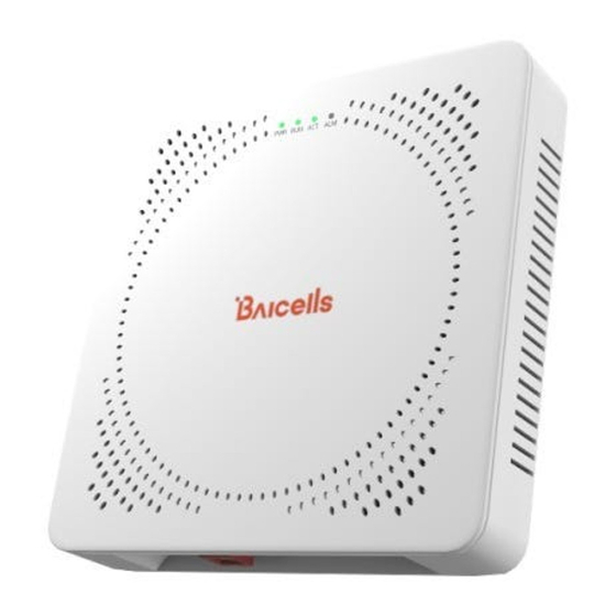
Overview 1.1 Introduction The Baicells Neutrino430 (Figure 1-1) is an advanced two-carrier indoor eNodeB that is compliant with Third-Generation Partnership Project (3GPP) on Long-Term Evolution (LTE) Time Division Duplex (TDD) technology. This 4x250mW eNodeB can operate in Carrier Aggregation (CA) mode or Dual Carrier (DC)/split mode. -
Page 8: Features
Baicells provides FCC Part 96 certified eNBs, including the Neutrino430, and CPEs that operate within the Part 96 rules for CBRS. The Baicells eNBs and CPEs use a Domain Proxy (DP) to connect to the SAS server by leveraging the existing connection with the OMC. - Page 9 HaloB User Guide • SAS Deployment Guide In addition to the Neutrino430 eNB two carriers and multiple operating modes, the following is a list of other key features. The Neutrino430 datasheet providing technical specifications is kept up- to-date on the Baicells website.
-
Page 10: Installation Preparation
Highly secured with equipment certification against potential intrusion risk Installation Preparation 2.1 Materials Check the Neutrino430 package to ensure it contains the primary components in the packout (Figure 2-1). In addition to industry-standard tools, you will need the tools described in Table 2-1. Figure 2-1: Packout... -
Page 11: Leds And Interfaces
Table 2-1: Installation Tools Level bar Marker pen Knife Pliers Percussion drill and Phillips-head Wrench Hammer drill heads screwdriver Cable vice 0.05 cm (5 mm) L- Tape measure T7 screwdriver head (crimper) shape Allen wrench 2.2 LEDs and Interfaces Figure 2-2, Table 2-2, and Table 2-3 explain the eNB's LED status indicators and interfaces. Figure 2-2: LEDs and Interfaces... -
Page 12: Location And Environment
2.3 Location and Environment The Neutrino430 can be installed on a ceiling or a wall. For the best signal coverage, place the eNB in an unobstructed location. In addition to network planning, when determining where to place the eNB, you need to consider the best location for signal coverage. Avoid locating the eNB in areas where there may be extreme temperatures, harmful gases, unstable voltages, volatile vibrations, loud noises, flames, explosives, or electromagnetic interference (e.g., large radar... -
Page 13: Cloudcore Account
2.4 CloudCore Account The Baicells CloudCore includes the Evolved Packet Core (EPC), managed by Baicells, and two operator applications, Operations Management Console (OMC) to manage network elements, and Business and Operation Support System (BOSS) to manage subscribers. If you have not already set up a Baicells CloudCore account, follow the steps below. -
Page 14: Install Enb On Ceiling Or Wall
The eNB unit bracket is assembled in manufacturing before packing. The only action required by the installer is to attach the assembly to the ceiling or wall. Follow the steps below to install the Neutrino430 eNB on the ceiling or wall. Caution: •... -
Page 15: Figure 3-4: Fix The Enb To The Wall Bracket
4. Slide the eNB along the arrow to fix it on the wall bracket (Figure 3-4). Figure 3-4: Fix the eNB to the Wall Bracket 5. Tighten the bolt on the top of the bracket using a Phillips-head screwdriver to complete the installation (Figure 3-5). -
Page 16: Connect Cables
RF power amplifier devices. The power and interface cables for the Neutrino430 can be connected in three different configurations depending on your specific site requirements or setup: PWR power supply, OPT backhaul, •... -
Page 17: Pwr Power Supply, Wan/Poe+ Backhaul Configuration
3.3.2 PWR Power Supply, WAN/PoE+ Backhaul Configuration: Connect the cables for the PWR power supply, WAN/PoE+ backhaul configuration, as shown in the following steps. Refer to Figure 3-7: 1. Connect the AC power supply to the power (PWR) interface on the eNB and the other end to a power outlet. -
Page 18: Power On To Check Led Status
3.4 Power on to Check LED Status After the Neutrino430 is powered on, check that the LED indicators are lighting as expected: Power is steady green, cell activated is slow flash green, and there are no alarms (Figure 3-9) per previous Table 2-2. -
Page 19: Launch The Enb Gui
3.5.1 Launch the eNB GUI Follow the steps below to connect to the Neutrino430 GUI. Step 1: Use an Ethernet cable to connect the eNB WAN/PoE+ port to the local network routed to the Internet. The DATA interface is set to DHCP client by default. -
Page 20: Upgrade Firmware
3.5.2.1 Upgrade Firmware from eNB GUI 1. Download the most recent firmware file from Baicells.com > Support > Firmware, and save on local computer. 2. Go to System > Upgrade, and select whether to preserve the current settings. -
Page 21: Basic Configuration Overview
3.5.2.2 Upgrade Firmware from the OMC 1. Go to eNB > Upgrade > Upgrade&Rollback. 2. Select the correct Product Type from the list. 3. Select the checkbox next to the eNB(s) you want to upgrade. 4. In the New Task window, select the Upgrade Type. 5. -
Page 22: Configure Network Interfaces
3.5.4 Configure Network Interfaces The network interfaces defined as part of the initial, basic setup include the WAN/LAN/VLAN interfaces, Dynamic Host Configuration Protocol (DHCP), and the Local Gateway (LGW) mode. 3.5.4.1 WAN/LAN/VLAN Go to the Network > WAN/LAN/VLAN menu (Figure 3-13). The WAN interface is an external communication portal (Internet connection) between the eNB Network Management System (NMS) –... -
Page 23: Figure 3-14: Lgw
3.5.4.2 LGW The Local GateWay (LGW) setting must be configured when using the Baicells CloudCore Evolved Packet Core (EPC). Refer to Figure 3-14 and Table 3-2. You must reboot the eNB when you make changes to these settings. -
Page 24: Table 3-2: Lgw
Table 3-2: LGW Field Name Description On or Off LGW Mode Select an option: NAT: Packages from the internal network to the external network need Network Address Translation Router: Select optimized route from the routing table (Figure 3-15) Bridge: Transfer in the data link layer LGW Interface Binding The IP address connects to the LGW. -
Page 25: Figure 3-15 Lgw = Router
Figure 3-15 LGW = Router 3.5.4.3 Static Routing When using static routing, go to Network > Static Routing. The Network > Static Routing landing page has two main sections, Static Routing Config and Validated Route List (Figure 3-16). The configured static route information is displayed under Static Routing Config. To edit a static route in the list, click on the edit icon, enter the information, and click OK. -
Page 26: Configure The Management Server
In the BTS Setting > Management Server window, you will enter the network management service (NMS) information (Figure 3-17). When using the Baicells CloudCore to manage the network, in the http:// field, enter the following URL address and port number: baiomc.cloudapp.net:48080/smallcell/AcsService... -
Page 27: Configure Quick Settings
Frequency will auto-fill based on the eNB hardware model. Make sure the Cloud EPC field is set to ON when using the Baicells CloudCore. If you are testing the eNB in a lab environment, turn the power down as low as it will go under the Power Modify field. -
Page 28: Figure 3-18: Quick Setting
NOTE 1: If planning to use CBRS SAS, the SAS vendor will determine some of these parameters. Refer to the SAS Deployment Guide for more information. NOTE Neutrino430 does not support SFA = 0. For a description of all the eNB Quick Setting fields, refer to the eNodeB Configuration Guide. -
Page 29: Configure Carrier Setting
Carrier Aggregation & Dual Carrier (Split Mode) Configuration Guide The Carrier Setting menu is used only in the two-carrier Neutrino430 eNB (Figure 3-19). You can set the eNB to run as a single carrier, as two combined carriers using Carrier Aggregation (CA), or as two independent carriers using Dual Carrier (DC)/split mode, depending on which licenses you have purchased. -
Page 30: Verify Enb Operational Status
Figure 3-20: Reboot 3.5.9 Verify eNB Operational Status When the eNB is finished rebooting, check the eNB status using the eNB GUI and the OMC: NOTE: Once the eNB is mounted at its intended destination and powered on, recheck the status settings. -
Page 31: Figure 3-21: Cell Status (Enb Gui)
Figure 3-21: Cell Status (eNB GUI) Figure 3-22: Cell Status (OMC) -
Page 32: Figure 3-23: Omc > Enb > Monitor > Display Settings
Figure 3-23: OMC > eNB > Monitor > Display Settings Before commercial operation, Baicells recommends implementing cell site acceptance testing of a new site to ensure the service meets expectations, to document network speeds at various locations in the cell, and to verify RF coverage. -
Page 33: Appendix: Regulatory Compliance
Appendix: Regulatory Compliance FCC Compliance This device complies with part 15 of the FCC Rules. Operation is subject to the following two conditions: (1) This device may not cause harmful interference, and (2) this device must accept any interference received, including interference that may cause undesired operation. Any Changes or modifications not expressly approved by the party responsible for compliance could void the user's authority to operate the equipment.
Need help?
Do you have a question about the Neutrino430 and is the answer not in the manual?
Questions and answers