
Related Manuals for Baicells Nova-233 G2


Summary of Contents for Baicells Nova-233 G2
- Page 1 Nova-233 G2 (mBS1105) Outdoor LTE TDD Base Station Installation Guide All rights reserved © Baicells Technologies Co., Ltd.
- Page 2 This document suits for the models of mBS11xx series base station. Copyright Notice Baicells copyrights this specification. No part of this specification may be reproduced in any form or means, without the prior written consent of Baicells. Disclaimer This specification is preliminary and is subject to change at any time without notice.
- Page 3 Contact Us Baicells Technologies Co., Ltd. Baicells Technologies North America, Inc. China North America Address 10-11F, Bldg. A1, No.1 Zhongguancun, 555 Republic Dr., #200, Plano, TX 75074, Yongfeng Industrial Base, Haidian Dist., Beijing, China Phone 400-108-0167 +1-888-502-5585 Email contact@Baicells.com sales_na@Baicells.com support@Baicells.com...
-
Page 4: Table Of Contents
Nova-233 G2 (mBS1105) Outdoor LTE TDD Base Station Installation Guide Table of Contents Product Overview ......................1 Introduction ......................1 Features ......................... 1 Appearance ......................2 Technical Specification.................... 3 1.4.1 Hardware Specification ................... 3 1.4.2 Software Specification ..................4 1.4.3 Environment Specification ................ - Page 5 3.6.2 Connect GPS Antenna..................15 3.6.3 Connect RF Cable ..................15 3.6.4 Connect Optical Fiber ..................15 3.6.5 Connect Ethernet Cable ................. 16 3.6.6 Connect Power Connector ................16 3.6.7 Connect Ground Cable .................. 17 Install Antenna Feeder System ................17 3.7.1 Install Omnidirectional Antennas ..............
- Page 6 Base Station Installation Guide List of Figures Figure 1-1 Nova-233 G2 Appearance ................2 Figure 1-2 Nova-233 G2 Interfaces and Indicators ............2 Figure 2-1 Installation Space Requirement ..............9 Figure 3-1 Installation Procedure of Nova-233 G2 ............ 11 Figure 3-2 Location of Grounding Screws..............17 Figure 3-3 Omnidirectional Antenna Installation (1) ...........
-
Page 7: Product Overview
1. Product Overview Introduction Baicells Nova-233 G2 is high performance outdoor micro base station based on LTE TDD technology, which is developed by Baicells. The Nova-233 G2 supports wired backhaul connections to backbone networks, and provides LTE access to user terminals, implemented voice and data service transmissions. -
Page 8: Appearance
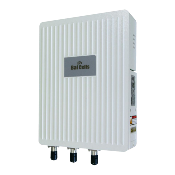
Appearance The Nova-233 G2 base station appearance is shown in Figure 1-1. Figure 1-1 Nova-233 G2 Appearance The Nova-233 G2 interfaces and indicators are shown in Figure 1-2. Figure 1-2 Nova-233 G2 Interfaces and Indicators... -
Page 9: Technical Specification
Optical interface, connect to external transmission network, used for data backhaul. RJ-45 interface, used for debug or data backhaul. ANT1 External antenna 1, N-female connector. The Nova-233 G2 interface indicators are described in Table 1-2. Table 1-2 Nova-233 G2 Interface Indicators Identity Color... -
Page 10: Software Specification
Item Description Receive Sensitivity -100 dBm Synchronization GPS, 1588 V2 Backhaul 1 Optical (SFP) and 1 RJ-45 Ethernet interface (1 GE) MIMO DL 2 x 2 Dimension 227mm (H) x 305mm (W) x 74mm (D) Installation Type Pole, wall External 18.5dBi directional antenna Vertical beamwidth: 35°... -
Page 11: Environment Specification
Item Description Interface ≥ 150000 hours MTBF ≤ 1 hour MTTR Support remote/local maintenance, based on SSH protocol Support remote maintenance Support online status management Support performance statistics Support failure management Support configuration management Support local or remote software upgrading and loading Maintenance Support log Support connectivity diagnosis... - Page 12 compliance could void the user's authority to operate the equipment. This equipment has been tested and found to comply with the limits for a Class B digital device, pursuant to part 15 of the FCC Rules. These limits are designed to provide reasonable protection against harmful interference in a residential installation.
-
Page 13: Installation Preparation
Nova-233 G2 (mBS1105) Outdoor LTE TDD Base Station Installation Guide 2. Installation Preparation Support Materials Prepare the following support materials accordingly, as given in Table 2-1. Table 2-1 Support Materials Item Description Power cable < AWG16 e.g. AWG14 Shorter than 100m Power plug The power plug connecting to the electricity supply. -
Page 14: Installation Environment
(large radar stations, transmitting stations, transformer substations) are not suitable for the operation of Nova-233 G2, and thus should be avoided. Places prone to have impounded water, soaking, leakage, or condensation, should also be avoided. -
Page 15: Personnel Requirements
Figure 2-1 Installation Space Requirement Personnel Requirements The installation personnel must master the basic safe operation knowledge, through the training, and having the corresponding qualifications. Against Lightening and Grounding Protection CAUTION It is unlikely to happen but since the LTE base station is very sophisticated equipment so we would recommend you to test it on the ground to make sure everything is functioning before install on the tower. -
Page 16: Weatherproof Protection
Rustproofing the terminals is required. This can be done with rust preventing paint, anti-oxidation coatings, grease, and so on. Weatherproof Protection The Nova-233 G2 adopts cold shrink tube for weatherproof protection. Before installing the cold shrink tube, clean up the interface first. The weatherproof protection steps are as follows: Insert cable into cold shrink tube. -
Page 17: Base Station Installation
Once unpacked, check whether the quantity are consistent with the packing list. Installation Procedure The installation procedure of Nova-233 G2 is given in Figure 3-1. Figure 3-1 Installation Procedure of Nova-233 G2 Install GPS Antenna Installation requirements on the GPS antenna: ... -
Page 18: Install On Pole
devices. Avoid interference from other transmitting antennas to the GPS antennas. Should be installed within 45 degrees to the lightning rod. The GPS has been assembled before packing, the only installation step is to fix the GPS mounting bracket on the base station using the M4 x 14 screws. Install on Pole Required diameter of the pole: 40mm ~ 100mm. - Page 19 As the following figure, hung the two pins on the base station bracket to the installation bracket, push the base station until the hook block to the base station bracket. Tighten two screws on the top of the bracket using cross screwdriver to complete the installation.
-
Page 20: Install On Wall
Install on Wall The wall must bear four times of the base station’s weight. Take apart the assembled installation bracket kit to get the installation bracket. Fit the bracket on the wall, and mark the drilling locations. Caution: The arrow of the installation bracket must be upward. Drill two 10mm diameter and 70mm depth holes in the wall on the marked locations, and insert the expansion pipes. -
Page 21: Connect Gps Antenna
The label should be paste after the cable laying. Optical fiber laying requirement: The circling and twisting is forbidden during the laying. The binding on the turning is forbidden. The pulling and weigh down the optical fiber is forbidden. ... -
Page 22: Connect Ethernet Cable
Lay optical fibers along the wire groove, and stretch out the wiring cavity from OPT hole. The redundant fiber should wind neatly. 3.6.5 Connect Ethernet Cable Connect the Ethernet cable to ETH interface in the wiring cavity. Lay Ethernet cable along the wire groove, and stretch out the wiring cavity from ETH hole. -
Page 23: Connect Ground Cable
3.6.7 Connect Ground Cable Make the grounding cable according the actual situation of the installation site. The Nova-233 G2 provides two grounding screws, which is located on the bottom of the base station, as shown in Figure 3-2. Figure 3-2 Location of Grounding Screws Unscrew one grounding screw, connect one end of the grounding cable to the grounding screw, and fasten it again. -
Page 24: Figure 3-3 Omnidirectional Antenna Installation (1)
that the antenna top falls within the 45 degrees safety angle towards the lightening rod, as shown in Figure 3-3. In principle, no lightening rod can be welded to pole (no metal object is allowed within 1m of the horizontal direction of the omnidirectional antennas), when installing the omnidirectional antennas. -
Page 25: Install Directional Antennas
3.7.2 Install Directional Antennas First, assemble the antennas, as shown in Figure 3-5. Figure 3-5 Assembling Procedure of Directional Antennas To install it on the iron tower, use a pulley to transport the antenna assembled to the platform on the iron tower, as shown in Figure 3-6. Following the safety rules when working at these heights. -
Page 26: Figure 3-7 Directional Antenna Installation
Figure 3-7 Directional Antenna Installation When the base station has been installed in a proper position, connect all the cables and wires. Run tests, then seal and weatherproof all the connections after the testing has successfully completed. Refer to 2.6 Weatherproof Protection. -
Page 27: Power On
Nova-233 G2 (mBS1105) Outdoor LTE TDD Base Station Installation Guide 4. Power On Power on the Nova-233 G2, and the indicators will light up, as shown in Figure 4-1. Figure 4-1 LED Indicators The explanation of the indicator signal is given in Table 4-1. - Page 28 Caution: This device complies with Part 15 of the FCC rules and Industry Canada license‐exempt RSS standard(s). Operation is subject to the following two conditions: (1) this device may not cause harmful interference, and (2) this device must accept any interference received, including interference that may cause undesired operation. The manufacturer is not responsible for any radio or TV interference caused by unauthorized modifications ...
Need help?
Do you have a question about the Nova-233 G2 and is the answer not in the manual?
Questions and answers