
Related Manuals for Smartgen GENSET CONTROLLER MGC310


Summary of Contents for Smartgen GENSET CONTROLLER MGC310
- Page 1 MGC310/MGC320 GENSET CONTROLLER USER MANUAL SMARTGEN (ZHENGZHOU) TECHNOLOGY CO., LTD.
- Page 2 SmartGen Technology at the address above. Any reference to trademarked product names used within this publication is owned by their respective companies. SmartGen Technology reserves the right to change the contents of this document without prior notice. Table 1 Version Hsitory Date...
-
Page 3: Table Of Contents
MGC300 Genset Controller User Manual CONTENT 1 OVERVIEW ............................4 2 PERFORMANCE AND CHARACTERS .................... 5 3 SPECIFICATION ..........................6 4 OPERATION ............................7 4.1 CONTROL PANEL ........................7 4.2 PUSH BUTTONS ........................8 4.3 INDICATOR DESCRIPTION ...................... 9 4.4 DISPLAY DISCRIPTION......................10 4.4.1 LOW POWER CONSUMPTION OPERATION .............. -
Page 4: Overview
MGC300 Genset Controller User Manual 1 OVERVIEW MGC300 Series Genset Controller is applicable for single unit automation control to realize auto start of single unit and AMF. The controller integrates digitalization with intelligence and applies LCD graphic display, which is simple for operation and reliable for running. MGC300 Series Genset Controller applies 32-bit micro-processor technology, realizing precise measuring for various parameters, set-value adjusting, and timing, and limit value setting functions etc. -
Page 5: Performance And Characters
MGC300 Genset Controller User Manual 2 PERFORMANCE AND CHARACTERS ——Graphic LCD display (backlight), LED indicators, push-button operation; ——Acrylic material for hard screen protection; ——Wide power supply range DC (8-35)V, which can suits different environments of starter battery voltages; ——Collect and display mains/gen 3-phase voltage, 3-phase current, frequency, and power parameters;... -
Page 6: Specification
MGC300 Genset Controller User Manual 3 SPECIFICATION Table 2 Technical Parameters Items Contents Working Voltage DC (8.0-35.0)V continous ≤1.4W (Standby mode: ≤0.35W, 0W=low power consumption); Overall Consumption AC Volt Input: 3 phase 4 wire 30V AC - 360V AC (ph-N) 3 phase 3 wire 30V AC - 620V AC (ph-ph) Single phase 2 wire... -
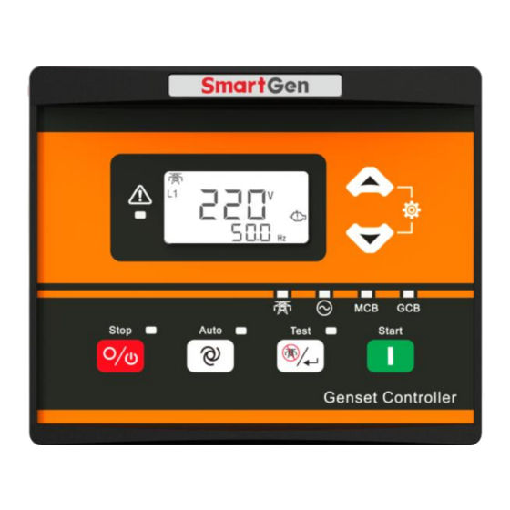
Page 7: Operation
MGC300 Genset Controller User Manual OPERATION 4.1 CONTROL PANEL Fig. 1 MGC310 Front Panel Fig. 2 MGC320 Front Panel MGC300 Genset Controller Version 1.1 2020-01-04 Page 7 of 27... -
Page 8: Push Buttons
MGC300 Genset Controller User Manual 4.2 PUSH BUTTONS Table 3 Button Description Icons Function Description Stop the running genset both in manual mode and in auto mode; In alarm status, press this button to reset any shutdown alarms. In stop mode, press this button and Up key to test if LCD icons and LED indicators are OK. -
Page 9: Indicator Description
MGC300 Genset Controller User Manual 4.3 INDICATOR DESCRIPTION Table 4 LCD Icons Icon Definition Icon Definition Generating power indicator Level sensor indicator Mains power indicator AC phase voltage indicator Start countdown (crank disconnect is AC line voltage indicator satisfied) Over frequency alarm Battery voltage indicator Under frequency alarm Load current unit... -
Page 10: Display Discription
MGC300 Genset Controller User Manual 4.4 DISPLAY DISCRIPTION Mains: Phase Voltage L1, Frequency F Mains: Phase Voltage L2, Frequency F Mains: Phase Voltage L3, Frequency F Gen: Phase Voltage L1, Curent IA Gen: Phase Voltage L2, Current IB Gen: Phase Voltage L3, Current IC Mains: Line Voltage L12, Frequency F Mains: Line Voltage L23, Frequency F Mains: Line Voltage L31, Frequency F... -
Page 11: Low Power Consumption Operation
MGC300 Genset Controller User Manual 4.4.1 LOW POWER CONSUMPTION OPERATION Controller applies low power consumption method at hardware aspect, which reduces the power consumption greatly in the period of stop. With this battery cost is larged decreased, because it reduces the battary change times. -
Page 12: Auto Stop Sequence
MGC300 Genset Controller User Manual 4.4.4 AUTO STOP SEQUENCE When remote start input is invalid, “Stop Delay” time is initiated; Once this “stop delay” has expired, the “Cooling Down Delay” is then initiated; When “Stop Idle Delay” (if configured) starts, idle speed relay is energized and outputs; When “ETS Solenoid Hold”... -
Page 13: Protection
MGC300 Genset Controller User Manual 5 PROTECTION Table 5 Alarm Types Icons Alarm Contents Type Trigger Over Frequency Stop Shutdown Gen frequency is above over frequency limit for 2s, it will issue alarm; Under Frequency Stop Shutdown Detected when genset is running normal; gen freq. is less than under frequency limit for 10s, and it alarms. -
Page 14: Connection
MGC300 Genset Controller User Manual 6 CONNECTION Fig. 3 Back Panel MGC300 Genset Controller Version 1.1 2020-01-04 Page 14 of 27... - Page 15 MGC300 Genset Controller User Manual Table 6 Terminal Connection Description Function Cable Size Note 1.5mm Connected with negative of starter battery. 1.5mm Connected with positive of starter battery. Fuel Relay Output 1.0mm B+ power is supplied by terminal 2, rated 7A. Crank Relay Output 1.0mm B+ power is supplied by terminal 2, rated 7A.
-
Page 16: Definition And Range Of Parameters
MGC300 Genset Controller User Manual 7 DEFINITION AND RANGE OF PARAMETERS 7.1 PARAMETER SETTING CONTENTS AND RANGE Table 7 Controller Configuration Parameters Items Parameter Range Default Description Mains Normal Delay (0-3600)s Check time duration for Mains voltage from Mains Abnormal abnormal to normal or from normal to (0-3600)s Delay... - Page 17 MGC300 Genset Controller User Manual Items Parameter Range Default Description complete stop; When engine speed is over this value for 2s, Generator Poles (2-64) over speed considered; controller issuesover speed alarm shutdown signal; Abnormal (0-20.0)s 10.0 Alarm delay for gen under/over voltage. Delay When generator voltage is higher than this threshold and lasts for the set gen abnormal...
- Page 18 MGC300 Genset Controller User Manual Items Parameter Range Default Description the temp. high alarm signal of input port); When level is under this value for 10s, level Level Low Warning low warning is issued (only warning, not (0-200)% Value stop); When battery voltage is higher than this Battery Over...
-
Page 19: Definable Contents Of Output Ports
MGC300 Genset Controller User Manual 7.2 DEFINABLE CONTENTS OF OUTPUT PORTS Table 8 Definable Contents of Output Ports Items Function Description When this is chosen, output port won’t output. Not Used Includes all shutdown alarms and warnings; when there is only warning Common Alarm alarm input, alarm is not latched;... -
Page 20: Sensor Selection
MGC300 Genset Controller User Manual 7.4 SENSOR SELECTION Table 9 Sensor Selection Items Contents Remark Temp. Sensor 0: Not Used Costomized resistance input range: 0Ω-6000Ω; Default: SGX Sensor 1: Customized Resistance Curve 2: VDO 3: SGH 4: SGD 5: CURTIS 6: DATCON 7: VOLVO-EC 8: SGX... -
Page 21: Controller Parameter Settings
MGC300 Genset Controller User Manual 8 CONTROLLER PARAMETER SETTINGS Under standby status, press at the same time, it will enter password entry screen (Fig. 4). At this moment the first digital flashes. Fig. 4 Password Entry Screen Press and the flashing number adds 1; Press and it decreases 1. -
Page 22: Sensor Setting
MGC300 Genset Controller User Manual 9 SENSOR SETTING Sensor types that can be connected inside controller are all resistance sensors; Parts of standard curves (Table 10) have been put inside the controller for users. If customized sensor curves are planned to use, users must set by PC software; When costomized sensor curve is set, X value (resistance) must be inputted from small to big, otherwise mistake may occur;... -
Page 23: Commissioning
AC generator’s voltage and frequency carefully. If there is something unusual, stop the running genset and check all wire connections according to this manual. f) For any other questions please contact with SmartGen service personnel. MGC300 Genset Controller Version 1.1... -
Page 24: Typical Application
MGC300 Genset Controller User Manual 11 TYPICAL APPLICATION Fig. 5 MGC310 Typical Application Diagram Fig. 6 MGC320 Typical Application Diagram CAUTION! Crank, fuel output ports shall expand big capacity relays; CAUTION! When sensor port is configured to "Figure High Input Active", hung up means High Electrical Level, and Power positive connected is prohibited. -
Page 25: Installation
MGC300 Genset Controller User Manual 12 INSTALLATION 12.1 FIXING CLIPS — The controller is panel-embedded design and the panels are fixed by clips in installation. — Twist the fixing clip screw anticlockwise until it reaches proper position. — Pull the fixing clip backwards (towards the back of the module), ensuring two clips are right inside their allotted slots. - Page 26 MGC300 Genset Controller User Manual Warning: When there is load current, CT secondary side open circuit is strictly prohibited. Withstand Voltage Test When the controller has been installed in the control panel, if the high voltage test is conducted, please disconnect controller’s all terminals in order to prevent high voltage entering controller and damaging it.
-
Page 27: Fault Finding
MGC300 Genset Controller User Manual 13 FAULT FINDING Table 10 Fault Finding Symptoms Possible Solutions Check starting batteries; Non response when controller is Check controller wirings; powered on. Check DC fuse; Check whether is pressed for 3s; Check water/cylinder temp. is too high or not; Genset shutdown Check AC generator voltage;...
Need help?
Do you have a question about the GENSET CONTROLLER MGC310 and is the answer not in the manual?
Questions and answers