
Related Manuals for Smartgen MGC120


Summary of Contents for Smartgen MGC120
- Page 1 MGC120 PETROL GENSET CONTROLLER USER MANUAL SMARTGEN (ZHENGZHOU) TECHNOLOGY CO., LTD.
- Page 2 SmartGen Technology at the address above. Any reference to trademarked product names used within this publication is owned by their respective companies. SmartGen Technology reserves the right to change the contents of this document without prior notice. Version Hsitory Date...
-
Page 3: Table Of Contents
MGC120 Petrol Genset Controller User Manual CONTENT 1 OVERVIEW ............................4 2 PERFORMANCE AND CHARACTERS .................... 4 3 SPECIFICATION ..........................5 4 OPERATION ............................6 4.1 CONTROL PANEL ........................6 4.2 INDICATOR DESCRIPTION ...................... 6 4.3 PUSH BUTTONS ........................7 4.4 AUTO START/STOP OPERATION ..................... -
Page 4: Overview
MGC120 Petrol Genset Controller User Manual 1 OVERVIEW MGC120 Petrol Genset Controller belongs to AMF module, which is suit for single petrol genset automation and monitoring control. It can realize auto start/stop genset, alarm protection and ATS switching control functions by data measuring. The controller applies LED display and button-press operation. -
Page 5: Specification
MGC120 Petrol Genset Controller User Manual 3 SPECIFICATION Table 2 Technical Parameters Items Contents Working Voltage Suitable for DC12V power supply system; Regular working:<2W(stepper motor is excluded) Overall Consumption Standby mode:<0.5W AC Volt Input: AC 30V - AC 360V (ph-N) -
Page 6: Operation
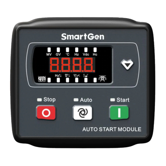
MGC120 Petrol Genset Controller User Manual OPERATION 4.1 CONTROL PANEL Fig. 1 Front Panel Description Start indicator: it is always light from genset start to normal running, and in other status, the indicator will extinguish. Stop indicator: it flashes when genset enters stop procedure; it is always light in the process of stop and in other status the indicator will extinguish. -
Page 7: Push Buttons
MGC120 Petrol Genset Controller User Manual 4.3 PUSH BUTTONS Table 4 Button Description Icons Function Description Stop the running genset both in manual mode and in auto mode, and change controller to the manual mode. In stop process, re-press this button to stop generator immediately. -
Page 8: Manual Start/Stop Operation
MGC120 Petrol Genset Controller User Manual Note: Press stop key in auto start status, generator will stop and enter into manual mode simultaneously. Total running timer starts when generator meets crank disconnection conditions, meanwhile, the last decimal point of the digital tube flashes to indicate that the generator is running. -
Page 9: Protection
MGC120 Petrol Genset Controller User Manual 5 PROTECTION Generator overvoltage shutdown: alarm occurs when the controller detects generator voltage exceeds overvoltage limit and the duration exceeds the generator abnormal delay value. Generator under voltage shutdown: the controller detects after genset normal running and when generator voltage is below under voltage limit and the duration exceeds the generator abnormal delay value alarm occurs. -
Page 10: Connection
MGC120 Petrol Genset Controller User Manual 6 CONNECTION Fig.2 Back Panel Table 5 Terminal Connection Description Function Cable Size Note 2.0mm Connected with negative of starter battery. Connected with positive of starter battery. 2.0mm Max. 20A fuse is recommended. B+ power is supplied by terminal 2, rated 10A. -
Page 11: Definition And Range Of Parameters
MGC120 Petrol Genset Controller User Manual Function Cable Size Note Generator Phase Voltage 1.0 mm Connect with generator voltage output port (2A fuse is (L-N) Monitoring Input 1.0 mm recommended) Note: the COM (red cable) for stepper motor shall be connected to battary positive. - Page 12 MGC120 Petrol Genset Controller User Manual Items Parameter Range Default Description The time for Stop electromagnet to be P14 ETS Solenoid Hold (0-120)s energized before genset stop. Pulse width for mains close and generator P15 Breaker Close Time (0-10.0)s close. 0s stands for constant output.
- Page 13 MGC120 Petrol Genset Controller User Manual Items Parameter Range Default Description shall open. If it is between the blocking value and opening value, the air flap opens 1/2. Default function: generator close output. For P28 Aux. Output 1 (0-9) details please see Table 8.
-
Page 14: Programmable Output Definable Contents
MGC120 Petrol Genset Controller User Manual Items Range Default Description 0: Fuel Output Fuel Output (0-1) 1: ETS Output Configure the function of controller terminal 6; Digital Input 1 (0-6) Default: remote start input, for details please see Table 9. -
Page 15: Controller Function Settings
MGC120 Petrol Genset Controller User Manual 8 CONTROLLER FUNCTION SETTINGS Under standby status, press for 3s, it will enter password entry screen (Fig. 3). At this moment the first digital flashes. Fig. 3 Password Entry Screen Press and the flashing number adds 1; Press and it decreases 1. -
Page 16: Commissioning
During this period, please observe engine’s running state, AC generator’s voltage and frequency carefully. If there is something unusual, stop the running genset and check all wire connections according to this manual. For any other questions please contact with SmartGen service personnel. MGC120 Petrol Genset Controller Version 1.2... -
Page 17: Typical Application
MGC120 Petrol Genset Controller User Manual 10 TYPICAL APPLICATION Fig. 5 MGC120 Typical Application Diagram 1 Notes: S11、S12、S21、S22 are separately connected with orange wire, pink wire, yellow wire, and blue wire, and stepper motor COM (red wire) shall be connected with the battery positive. - Page 18 MGC120 Petrol Genset Controller User Manual Fig. 6 MGC120 Typical Application Diagram 2 Notes: Programmable output 1 shall be set “Generator Close Output”. S11, S12, S21, S22 shall be connected separately with the stepper motor orange wire, pink wire, yellow wire and blue wire;...
-
Page 19: Installation
Fig. 7 Overall and Cutout Dimensions Battery Voltage Input MGC120 controller is only suitable for DC12V battery voltage environment. battery Negative must be connected with the engine shell soundly. The diameter of the wire which connects controller power B+/B- and battery positive/negative must be over (or equal to) 1.5mm . -
Page 20: Fault Finding
MGC120 Petrol Genset Controller User Manual 12 FAULT FINDING Table 10 Fault Finding List Symptoms Possible Solutions Check starting batteries; Non response when controller is Check controller connecting wirings; powered on. Check DC fuse. Check AC generator voltage. Genset shutdown Low oil pressure alarm after Check oil pressure sensor and the wirings.
Need help?
Do you have a question about the MGC120 and is the answer not in the manual?
Questions and answers