Table of Contents
Advertisement
Quick Links
Advertisement
Table of Contents

Related Manuals for Smartgen MGC100


Summary of Contents for Smartgen MGC100
- Page 1 MGC100 PETROL GENSET CONTROLLER USER MANUAL...
-
Page 2: Table Of Contents
8.1 PARAMETERS REGULATION ....................... 14 8.2 RESTORE FACTORY SETTINGS ......................14 8.3 ELIMINATE ACCUMULATED TIME ...................... 14 9 CASE DIMENSIONS ............................. 15 10 TYPICAL APPLICATION ..........................16 11 FAULT FINDING ............................16 MGC100 Petrol Genset Controller User Manual Page 2 of 16... - Page 3 SmartGen Technology at the address above. Any reference to trademarked product names used within this publication is owned by their respective companies. SmartGen Technology reserves the right to change the contents of this document without prior notice. Table 1 Version Hsitory Date...
- Page 4 Indicates a procedure or practice, which, if not strictly observed, could result in CAUTION! damage or destruction of equipment. Indicates a procedure or practice, which could result in injury to personnel or loss of life if not followed correctly. WARNING! MGC100 Petrol Genset Controller User Manual Page 4 of 16...
-
Page 5: Overview
1 OVERVIEW MGC100 Petrol Genset Controller is designed for start and protection of single genset. It allows manual and remote start/stop, data measurement, alarm indication, shutdown protection functions. The controller fit with LED display, button-press operation, and it achieves precise measurement of various parameters, protection and control of genset. -
Page 6: Specification
Storage Temperature (-25~+70)°C Protection Level IP55 Gasket Apply AC2.2kV voltage between high voltage terminal and low Insulation voltage terminal; The leakage current is not more than 3mA within 1min. Weight MGC100 Petrol Genset Controller User Manual Page 6 of 16... -
Page 7: Operation
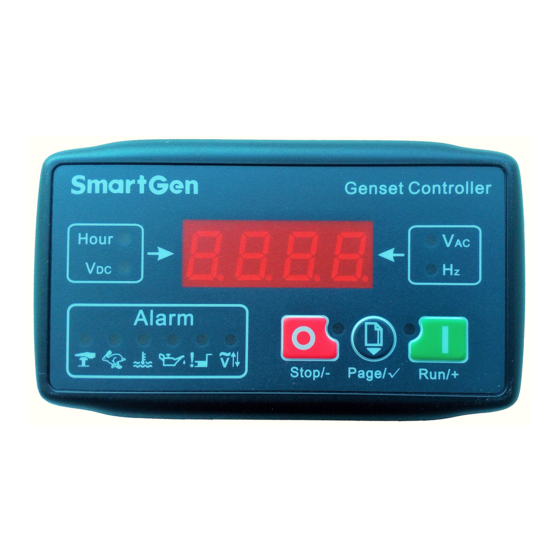
Manual start in stop status. Run/+ In setting menu, downturn or increase parameter value (it can be double-clicked). 4.2 CONTROL PANEL AND ICON DECRIPTION 4.2.1 CONTROLLER PANEL Fig.1 Controller Panel MGC100 Petrol Genset Controller User Manual Page 7 of 16... -
Page 8: Alarm Icon Indication
“ETS Solenoid Hold” begins, ETS relay is energized while fuel relay is de-energized; “Fail to Stop Delay” begins, complete stop is detected automatically; Genset is placed into standby mode after its “After Stop Time”. MGC100 Petrol Genset Controller User Manual Page 8 of 16... -
Page 9: Manual Start/Stop
Gen Over Frequency: Detection when start genset, if gen frequency exceeds over frequency value and the “over frequency” delay has expired, over frequency shutdown alarm will be sent. MGC100 Petrol Genset Controller User Manual Page 9 of 16... -
Page 10: Connection
Connected with W phase (2A fuse is recommended). V phase voltage monitor 1.0mm Connected with V phase (2A fuse is recommended). U phase voltage monitor 1.0mm Connected with U phase (2A fuse is recommended). MGC100 Petrol Genset Controller User Manual Page 10 of 16... -
Page 11: Definition And Range Of Parameters
Time between ending of pump unit idle delay Stop Time (0-120)s and stopped when “ETS Time” is set as 0; Time between ending of ETS hold delay and MGC100 Petrol Genset Controller User Manual Page 11 of 16... - Page 12 0) Over Freq (0-60)s Gen over frequency delay value. Shutdown Delay CLb1 Correct A phase voltage value. CLb2 Correct B phase voltage value. CLb3 Correct C phase voltage value. MGC100 Petrol Genset Controller User Manual Page 12 of 16...
- Page 13 If genset without magnetic sensor, please don’t select corresponding items, otherwise, “Start Failure” may be caused. If generate isn’t selected, the controller won’t detect over/under voltage; if magnetic sensor isn’t selected, speed of genset is converted via generate signal. MGC100 Petrol Genset Controller User Manual Page 13 of 16...
-
Page 14: Parameters Setting
——Number of setting contents refers to “Parameter Content and Range (Table 7)”. ——Only in parameter number menu can exit from parameter setting status. If there is no press operation in parameter number menu, it will exit in 30s automatically. MGC100 Petrol Genset Controller User Manual Page 14 of 16... -
Page 15: Case Dimensions
Battery Voltage Input NOTE: MGC100 controller can suit for widely range of battery voltage DC(9~18)V. Negative of battery must be connected with the engine shell soundly. The diameter of wire which from power supply to battery must be over 1.0mm If floating charge configured, please firstly connect output wires of charger to battery’s positive and negative directly,... -
Page 16: Typical Application
Refer to engine manual. Check related switch and its connections according to the Shutdown alarm in running information on LED. Check starter connections; Starter no response Check starting batteries. _________________________________ MGC100 Petrol Genset Controller User Manual Page 16 of 16...
Need help?
Do you have a question about the MGC100 and is the answer not in the manual?
Questions and answers
как посмотреть моточасы на контролере что нажимать