
Subscribe to Our Youtube Channel
Related Manuals for Edgetech 3400


Summary of Contents for Edgetech 3400
- Page 1 3400 PORTABLE SUB-BOTTOM SYSTEM U S E R H A R D W A R E M A N U A L 0021270_REV_A 1/23/2020 EdgeTech 4 Little Brook Road West Wareham, MA 02576 Tel: (508) 291-0057 Fax: (508) 291-2491 www.EdgeTech.com...
- Page 2 The information, figures, and specifications in this manual are proprietary and are issued in strict confidence on condition that they not be copied, reprinted, or disclosed to a third party, either wholly or in part, without the prior, written consent of EdgeTech. Any reproduction of EdgeTech supplied software or file sharing is strictly prohibited.
-
Page 3: Attention - Read This First
ATTENTION – READ THIS FIRST! All personnel involved with the installation, operation, or maintenance of the equipment described in this manual should read and understand the warnings and cautions provided below. CAUTION! This equipment contains devices that are extremely sensitive to static electricity. -
Page 4: Hardware Variations And Compatibility
Although the component manufacturers—along with their models and styles—may change from unit to unit, replacement parts will generally be interchangeable. EdgeTech will make every effort to see that replacement components are interchangeable and use the same software drivers (if applicable). At times, however, direct replacements may not exist. When this happens, EdgeTech will provide the necessary drivers with the replacement part, if applicable. -
Page 5: About This Document
ABOUT THIS DOCUMENT We, the employees at EdgeTech, would like to thank you for purchasing 3400. At EdgeTech, it is our policy to provide high-quality, cost-effective products and support services that meet or exceed your requirements. We also strive to deliver them on-time and to look for ways to improve them. We take pride in the products we manufacture and want you to be entirely satisfied with your equipment. -
Page 6: Warranty Statement
All equipment manufactured by EdgeTech is warranted against defective components and workmanship for a period of one year after shipment. Warranty repair will be done by EdgeTech free of charge. Shipping costs are to be borne by the customer. Malfunction due to improper use is not covered in the warranty, and EdgeTech disclaims any liability for consequential damage resulting from defects in the performance of the equipment. -
Page 7: Software Service Overview
Software Updates and Enhancements EdgeTech customers can download new software releases with all modifications and enhancements from the EdgeTech FTP site. Major software issues, should they occur, will be reported directly to the customer. New software releases consist of the following: Software enhancements that are not on the price list •... -
Page 8: Returned Material Authorization
Refer to the RMA number on all documentation and correspondences. All returned materials must be shipped prepaid. Freight collect shipments will not be accepted. All equipment should be adequately insured for shipping, but equipment belonging to EdgeTech must be insured for full value. - Page 9 CUSTOMER SERVICE Customer service personnel at EdgeTech are always eager to hear from users of our products. Your feedback is welcome and a valuable source of information that we use to improve these products. Therefore, we encourage you to contact EdgeTech Customer Service to offer any suggestions or to request...
-
Page 10: Company Background
— for the acquisition of underwater data, including marine, estuarine, and coastal applications — for over 50 years. EdgeTech responds to the needs of the Scientific, Naval, and Offshore communities by providing industry- leading equipment — such as Sub-Bottom Profilers, Side Scan Sonar, Acoustic Releases, USBL Positioning Systems, and Bathymetric Systems —... -
Page 11: Table Of Contents
TABLE OF CONTENTS ........................... xi LIST OF FIGURES ..........................xv LIST OF TABLES ..........................xviii OVERVIEW ..........................1-1 Key Features of the 3400 Sub-Bottom Profiling System ............1-1 1.1.1 CHIRP Transmission ......................1-1 1.1.1.1 Advantages of Full Spectrum CHIRP Technology ............1-2 1.1.2... - Page 12 1.3.1 3400 Rack Mounted Topside in Case and Ruggedized Laptop ........... 1-10 1.3.2 3400 Cable .......................... 1-11 1.3.3 3400 Towfish ........................1-11 1.3.4 3400 Pole Mounting Kit ...................... 1-12 1.3.5 3400 Options........................1-13 1.3.5.1 Amplifier Option ......................1-13 SPECIFICATIONS ........................2-14 Towfish Specifications ......................
- Page 13 4.5.2 3400 Portable Topside Connection and Activation ............4-40 4.5.2.1 Connecting 3400 System Components ............... 4-40 4.5.2.2 Connecting 3400 Systems Components and Optional Amplifier....... 4-41 4.5.2.3 Making an Ethernet Connection ................. 4-41 4.5.2.4 Activating the System ....................4-42 4.5.3 Performing Sub Bottom Pre-Deployment Checks ..............
- Page 14 5.5.2 Removing the Sonar Processor Bottle ................5-73 5.5.3 Adding or Removing Weights ..................... 5-75 Computer System Restoration ....................5-79 TROUBLESHOOTING....................... 6-80 KITS ............................7-81 3400 Portable Sub-bottom System 0021270_REV_A...
-
Page 15: List Of Figures
Figure 3-4: Sonar Processor Endcap Diagram ..................3-25 Figure 3-5: 3400 Electronics Bottle Pinouts ..................... 3-26 Figure 3-6: Sub Cable T Splice 3400 SBP Tow Cable to Bottle, Transformer, and Tow Cable....3-27 Figure 3-7: 3400 SBP 50 Meter Tow Cable....................3-28... - Page 16 Figure 3-13: Amplifier Rack Mount ICD ....................3-33 Figure 3-14: Amplifier Back Panel Interface to 3400 ................3-34 Figure 3-15: Amplifier Connection Diagram (3400 OTS Towfish Variant Depicted- Connections Are The Same Regardless of Variant) ........................3-35 Figure 3-16: Amplifier to 3400 Topside Interface Cable ................3-36 Figure 4-1: 3400 Topside Serial Port Navigation Connection ..............
- Page 17 Figure 5-2: Electronic Bottle Latch and Rubber Strip Locations .............. 5-74 Figure 5-3: 3400 Front Panel Removal With Screws To Be Removed Called Out (12) ......5-75 Figure 5-4: 3400 Weight Removal-Location of Bolt Hardware Top of Vehicle ........5-76 Figure 5-5: 3400 Weight Removal-Location of Bolt Heads on Bottom of Vehicle ........
- Page 18 Table 2-7: Amplifier Option Electrical Specifications ................2-16 Table 2-8: 50-Meter Tow Cable Specification ..................2-17 Table 3-1: 3400 Topside Front Panel Indicator Light and Switch Descriptions ........3-30 Table 3-2: 3400 Topside Back Panel Switches and Connections ............. 3-31 Table 3-3: Amplifier Front Panel Controls and Indicator Lights ...............
-
Page 19: Overview
The system generates high-resolution images of the sub-bottom stratigraphy in oceans, lakes, and rivers and provides excellent penetration in various bottom types. The EdgeTech 3400 comes in a dual 2-16 kHz transducer configuration. The towfish is configured with new PVDF receiver arrays segmented for standard sub-bottom profiling operations or a unique “pipeliner”... -
Page 20: Advantages Of Full Spectrum Chirp Technology
All these advantages are discussed in detail below. Separate Acoustic Projectors and Receivers The 3400 Sub-Bottom Profiling System uses acoustic projectors and receivers mounted in a towed vehicle to transmit and receive acoustic FM pulse signals. The projectors are wideband piston-type transducers, and the receivers are hydrophone arrays composed of polyvinylidene difluoride (PVDF) hydrophones. - Page 21 Additional Processing Gain Edgetech CHIRP technology achieves a signal processing gain over the background noise. This gain is approximately ten times the log of the time-bandwidth product. This improvement is due to the signal having a time duration longer than the inverse of the bandwidth, thus increasing signal energy without increasing the power of the outgoing pulse.
-
Page 22: Dual Wideband Transmitters
1.1.2 Dual Wideband Transmitters The EdgeTech 3400 comes standard in a dual 2-16 kHz transducer configuration that provides an increased source level and beam pattern. Sub-Bottom Transducers Figure 1-1: 3400 Sub-Bottom Transducers 1.1.3 Dual Frequency Transmission Dual alternating pulse technology provides users with the capability to transmit two different sub-bottom pulses over the same survey line in a single pass. -
Page 23: Enhanced Sub-Bottom Multi-Channel Pvdf Receiver
Figure 1-2: Discover 3400 High (Yellow) and Low (Blue) Sub-Bottom Displays 1.1.4 Enhanced Sub-Bottom Multi-Channel PVDF Receiver Edgetech’s PVDF receivers have advantages over other systems. The segmented arrays provide for different modes of operation from sub-bottom profiling to very specific applications like “Pipeliner Mode”... -
Page 24: Figure 1-3 3400 Pvdf Receiver
PVDF Receiver Figure 1-3 3400 PVDF Receiver Figure 1-4: Traditional Hydrophone with Side-Lob Echoes 3400 Portable Sub-bottom System 0021270_REV_A... -
Page 25: Figure 1-5: 3400 Pvdf Imagery Side Lobes With Reduces Echoes
Figure 1-5: 3400 PVDF Imagery Side Lobes with reduces Echoes Figure 1-6: Comparison of 3400 Vs. Traditional Line Arrays Over Same Survey Line... -
Page 26: Sub-Bottom Of "Pipeliner" Mode
(up to 30 Hz) for better detection and measurement of the shallow buried pipe/cable. The Pipeline Mode feature of the 3400 can also be used to detect boulders, UXO, buried hazards, or other debris for site clearance and route surveys. -
Page 27: Surface Echo Attenuation
1.1.7 Pulse Library Tailored for Most Survey Applications The 3400 pulse library includes both FM and BOOST pulses to collect the best datasets on a variety of seafloors. BOOST pulses emphasize the low end of the bandwidth that should exhibit better performance in deeper water than standard FM pulses. -
Page 28: 3400 Applications
Map, measure & classify sediment layers within the seafloor 1.3 Main System Components The 3400 system is composed of three primary components: a rack-mounted 3400 topside with a connected laptop, a 3400 towfish, and a customer supplied tow cable to connect the two. -
Page 29: 3400 Cable
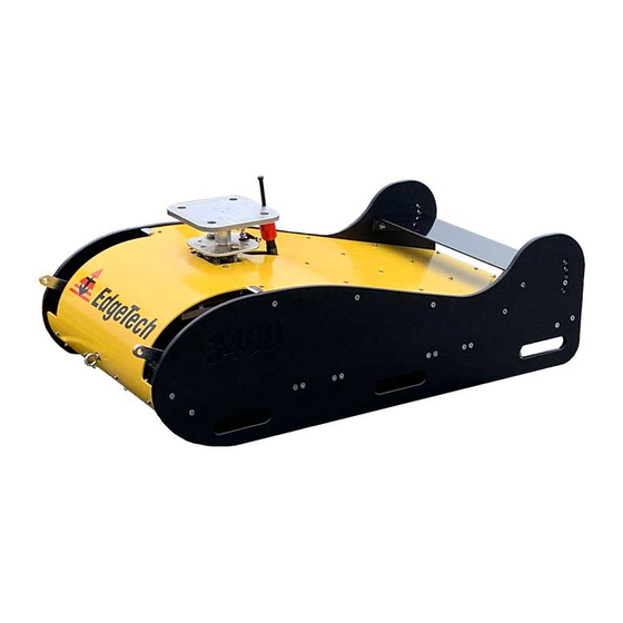
Figure 1-10: Tow Cable 1.3.3 3400 Towfish The 3400 is a hydrodynamic towfish designed to carry dual 2-16 kHz transducers and a large segmented PVDF array for sub-bottom surveys. The vehicle is stable, durable, and portable enough to be easily maneuvered on deck and in the water. -
Page 30: 3400 Pole Mounting Kit
The 3400 Pole Mounting Kit is necessary to mount the towfish using an EdgeTech designed mount attachment plate to a user-supplied pole. The 3400 Pole Mounting kit is delivered with a pole mount flange, Kevlar deck cable, and tool kit. Users must further secure a pole mounted system to their vessel using taut safety lines and the vehicles auxiliary tow points. -
Page 31: 3400 Options
1.3.5 3400 Options 1.3.5.1 Amplifier Option The 3400 Amplifier option integrates amplifier into the 3400 system providing increased power to the towfish transducers depending on the amplifier model purchased. Increased power improves penetration and deeper water performance. Figure 1-17: Amplifier in Case... -
Page 32: Specifications
2-14 2.0 SPECIFICATIONS The specifications for the 3400 Sub-Bottom Profiling System include electrical, mechanical, and environmental characteristics for the Portable Topside Processor, Laptop, 3400 Tow Vehicle, and the 50 Meter Tow Cable. 2.1 Towfish Specifications 2.1.1 3400 Sonar Specifications SONAR SPECIFICATIONS... -
Page 33: 3400 Topside Specifications
Pin 2= Transmit data to PC. • Use Straight cable to connect to PC. Pin 3= Receive data from PC. • All serial ports wired as DCE except port #1 Pin 5=Ground wired as DTE. Table 2-4 3400 Topside Specifications... -
Page 34: Edgetech Laptop Computer Specifications
Input Power 20AMP Power to Towfish To Be Determined Amplifier Interface cable 0022676 3400 OTS I/O Ports Interface Cable between 3400 Sea Cable Port and 3400 Amplifier Interface Panel Table 2-7: Amplifier Option Electrical Specifications 3400 Portable Sub-bottom System 0021270_REV_A... -
Page 35: 3400 Kevlar Tow Cable Specifications
2-17 2.2.2 3400 Kevlar Tow Cable Specifications The 3400 Tow Cable Specifications are shown below: SPECIFICATION VALUE Construction Mylar, Kaptamid, Telethane, Polypropylene, Aluminium, Copper Maximum Length 50 m (164ft) ; (75m Max) Weight In Air 94 kg/100 m (207 lb/1000 ft) Breaking Strength 544.3 kg (1200 lb) minimum... -
Page 36: Mechanical Drawings
2-18 2.2.3 Mechanical Drawings 2.2.3.1 3400 Towfish ICD Figure 2-1: 3400 Towfish ICD 3400 Portable Sub-bottom System 0021270_REV_A... -
Page 37: 3400 Topside Icd
2-19 2.2.3.2 3400 Topside ICD Figure 2-2: 3400 Topside ICD... -
Page 38: 3400 Topside Case Icd
2-20 2.2.3.3 3400 Topside Case ICD Figure 2-3 3400 Topside Case ICD 3400 Portable Sub-bottom System 0021270_REV_A... -
Page 39: 3400 Pole Mount Flange Icd
2-21 2.2.3.4 3400 Pole Mount Flange ICD Figure 2-4: Pole Mount Flange... -
Page 40: 3400 Technical Descriptions
PVDF sub-bottom receiver and an internal sonar processor. The towfish receives power and data from a tow cable that connects to the 3400 Topside on a survey vessel. Sonar signal is generated by the transducers, received by the PVDF receiver, amplified, digitized, and combined with towfish sensor data before being sent to to the 3400 topside processor. -
Page 41: 3400 System Connection Diagram
3-23 3.1.1 3400 System Connection Diagram Figure 3-2: 3400 System Connection Diagram... -
Page 42: Electronics Bottle And End Cap Diagrams
3-24 3.1.2 Electronics Bottle and End Cap Diagrams Figure 3-3: 3400 Electronics Bottle ICD 3400 Portable Sub-bottom System 0021270_REV_A... -
Page 43: Figure 3-4: Sonar Processor Endcap Diagram
3-25 Figure 3-4: Sonar Processor Endcap Diagram... -
Page 44: Figure 3-5: 3400 Electronics Bottle Pinouts
3-26 Figure 3-5: 3400 Electronics Bottle Pinouts 3400 Portable Sub-bottom System 0021270_REV_A... -
Page 45: Cable And Connector Diagrams
3-27 3.1.3 Cable and Connector Diagrams Figure 3-6: Sub Cable T Splice 3400 SBP Tow Cable to Bottle, Transformer, and Tow Cable. -
Page 46: Figure 3-7: 3400 Sbp 50 Meter Tow Cable
3-28 Figure 3-7: 3400 SBP 50 Meter Tow Cable 3400 Portable Sub-bottom System 0021270_REV_A... -
Page 47: Figure 3-8: Tow Cable Connector Pinouts
3-29 Figure 3-8: Tow Cable Connector Pinouts... -
Page 48: 3400 Portable Topside Technical Description
3.2 3400 Portable Topside Technical Description The 3400 portable topside provides power to the towfish while acting as a digital link between the towfish and a topside computer with the Discover application on it to process and record sonar data. The digital link also provides input connections for supporting survey, navigation devices, and triggers. -
Page 49: 3400 Amplifier Option Technical Description
Figure 3-10: 3400 Topside Rear Panel 3.3 3400 Amplifier Option Technical Description The 3400 Amplifier option integrates an amplifier into the 3400 system providing increased power to the towfish transducers depending on the amplifier model purchased. Increased power improves penetration and deeper water performance. -
Page 50: Figure 3-12: Back Panel Amplifier And Connector Panel
BACK CONNECTOR PANEL A pin-out MS3102A-20-27P connector that connects the amplifier to the J1 3400 I\O Connector 3400 topside Sea Cable port using the amplifier interface cable. J2 Sea Cable Connector A pin-in MS3102A-20-27S connector that connects to the vehicle sea cable. -
Page 51: Amplifier Rack Mount
3-33 3.3.1 Amplifier Rack Mount Figure 3-13: Amplifier Rack Mount ICD... -
Page 52: Figure 3-14: Amplifier Back Panel Interface To 3400
3-34 Figure 3-14: Amplifier Back Panel Interface to 3400 3400 Portable Sub-bottom System 0021270_REV_A... -
Page 53: Amplifier Connection Diagram
3-35 3.3.2 Amplifier Connection Diagram Figure 3-15: Amplifier Connection Diagram (3400 OTS Towfish Variant Depicted- Connections Are The Same Regardless of Variant) -
Page 54: Amplifier Cable Diagram
3-36 3.3.3 Amplifier Cable Diagram Figure 3-16: Amplifier to 3400 Topside Interface Cable 3400 Portable Sub-bottom System 0021270_REV_A... -
Page 55: Setup And Activation
Review the packing list and verify all the listed items are included. Again, if any damage is found, report it to the carrier and EdgeTech. If any items are missing, immediately contact EdgeTech. Do not install or operate any equipment that appears to be damaged. -
Page 56: Power Requirements
Navigation System. The devices are connected to the system by plugging them into the COM A or COM B serial ports located on the rear panel of the 3400 Topside. Optionally they could be connected to the serial port of the computer as well. -
Page 57: 3400 Portable Topside Placement
Tow Vehicle. Connecting the System Components WARNING! NEVER attempt to tow or lift the 3400 Tow Vehicle with the eye bolts at the nose or tail. These are to be used for auxiliary safety lines. WARNING! Do not connect the tow cable to the 3400 Portable Topside before connecting it to the tow vehicle;... -
Page 58: 3400 Portable Topside Connection And Activation
4.5.2 3400 Portable Topside Connection and Activation 3400 S The following procedure describes how to connect the 3400 Portable Topside system. A YSTEM is provided in the section of this manual to assist. -
Page 59: Connecting 3400 Systems Components And Optional Amplifier
1. Check to make sure the power entry module is in the Off position, and the front panel switch is in the off position before connecting supplied AC Power Cable (switch position = DOWN). 2. Connect the 3400 Topside to a source of AC power using the AC power cable. (Check system power specifications). -
Page 60: Figure 4-3: 3400 Network Configuration Diagram
EdgeTech advises that any Laptop (or Desktop) intended to connect to the 3400 Topside must, therefore, use a TCP/IP address 192.9.0.xxx where xxx is in the range 64 to 100. EdgeTech Factory defaults for EdgeTech Laptop is 192.9.0.99 for the Ethernet LAN. -
Page 61: Figure 4-4: 3400 Topside Front Panel-Led Indicator Lights
A red Power Indicator LED. When illuminated, AC power is applied to the Power Button Light topside. A green Link indicator LED. Flashes, while the 3400 Topside is establishing a reliable communications link with the side-scan sonar. Illuminates Link Indicator Light continuously when a reliable communications link with the sonar is established. -
Page 62: Activating The System
4-44 back and navigation is present. The Discover 3400 Application Windows is shown in the figure below, and the results of a tap test are displayed in 4-9. IGURE NOTE: See the Discover 3400 Software Manual for detailed software information. -
Page 63: Figure 4-7: Towfish Control Tab-Pulse And Transmit Level Called Out
4-45 transmitting. The transducers should begin transmitting (at 100%) and receive data should begin scrolling on the Waterfall Display in Discover Sub-Bottom, from right to left. Figure 4-7: Towfish Control Tab-Pulse and Transmit Level Called Out 4. In the Towfish Control Tab, select a Transmit Pulse using the “Pulse” dropdown. Set “Transmit Level (%)”... -
Page 64: Tow Vehicle Deployment
4.6 Tow Vehicle Deployment The 3400 tow vehicle can be towed using the tow cable purchased with the vehicle. The towfish end of the cable should be secured to the bridle shackle with the cable grip, and the tow cable is then run down along a towfish bridle arm to the connector where both ends are mated. -
Page 65: Figure 4-10: 3400 Tow Cable Grip Bridle Shackle Attachment
4-47 Figure 4-10: 3400 Tow Cable Grip Bridle Shackle Attachment Figure 4-11: Towfish Deployment... -
Page 66: Obtaining The Best Sonar Imagery When Towing
-6-dB beamwidth at 10 kHz is 20 degrees. For example, if you are transmitting a 2 to 15 kHz FM pulse using a Tow Vehicle with a 0.5-meter long receiving array, such as in the 3400 Tow Vehicle, you must keep the Tow Vehicle from pitching more than about 7 degrees in either direction, or ����... -
Page 67: Conducting Sediment Classification Surveys When Towing
The following towfish layback charts are provided to assist in towing. Please take the following points into consideration if they are used: • The standard 3400 towfish currently supports depths no greater than 100 meters. • The results listed in these tables are calculated using the Woods Hole WHOI cable program with best-estimated parameters for vehicle weight, drag, lift, and buoyancy, as well as cable weight and stiffness. -
Page 68: Table 4-3: 3400 25-Meter With Lead Pack Installed Layback Chart
The values contained in these charts are subject to change and have been assigned an error of +/- • 10%. Keep this in mind, especially if within 10% of the endpoint of any parameter. TOWED 3400 WITH LEAD WEIGHT PACK INSTALLED AND 25 METERS OF CABLE TCSC100942 PAID OUT Down Angle... -
Page 69: U-Hinge Tow Bridle
4-51 TOWED 3400 WITH LEAD WEIGHT PACK INSTALLED AND 50 METERS OF CABLE TCSC100942 PAID OUT Down Angle Speed Speed Cable Paid Out Max Cable Depth Distance Behind from Horiz. (kts) (m/s) Tension (N) Ship (m) (deg) 2.00 1.03 2.50 1.29... -
Page 70: U-Hinge Tow Bridle Removal Instructions
The bolts and cotter rings can be accessed through the handhold holes on the forward port and forward starboard side panels of the towfish or by propping the fish up on to skids and reaching underneath the vehicle. 3400 Portable Sub-bottom System 0021270_REV_A... -
Page 71: Figure 4-14: Nut And Bolt Location Looking Through Handhold Hole
4-53 [2]Cotter Rings Figure 4-14: Nut and Bolt Location Looking Through Handhold Hole... -
Page 72: Figure 4-15: Bridle Arm Bolt Locations- 2 Bolts Port And Starboard Sides
4-54 [2]1/2 Bolts Figure 4-15: Bridle Arm Bolt Locations- 2 Bolts Port and Starboard Sides 3400 Portable Sub-bottom System 0021270_REV_A... -
Page 73: Figure 4-16: Bridle Removal Tool Orientation
4-55 Figure 4-16: Bridle Removal Tool Orientation 2. Through the top of the towfish, remove [2] 1/2” inch bolts both port and starboard side mountings using 3/8 Socket wrench with extension and 3/8” bit with 5/32” Ball End socket. To hold the nuts securing the bolts, access the fish with a wrench through the forward side panel handhold holes. -
Page 74: Figure 4-17: Bridle Removal: Cotter Ring Removal
Figure 4-17: Bridle Removal: Cotter Ring Removal 2. Remove left and right 1/2 inch bolt, 1/2 inch nut, and washers using 3/4” wrenches or adjustable crescent wrenches. This will separate the bridle from the towfish at the elbows. 3400 Portable Sub-bottom System 0021270_REV_A... -
Page 75: Pole Mounting
4-57 Figure 4-18: Bridle Removal-Elbow Hardware Removal 3. Lift bridle away and store. 4.9 Pole Mounting If you purchased this option, the Pole Mount Flange comes preinstalled. Should you need to install or remove the Pole Mount for any reason, instructions for that are written below. NOTE: Remove the elevator from the vehicle when pole mounting, following the procedure outlined in... - Page 76 (4) 3/4”-10 Hex Nuts • • (4) 3/4” Split Lock Washer (4) 3/4” Flat Washer • • (4) 3/4”-10 Hex Head Screw • (1) 7/8” Split Lock Washer • (1) 7/8”-9 Hex Nuts • (1) Cable Tie 3400 Portable Sub-bottom System 0021270_REV_A...
-
Page 77: Figure 4-19: Tow Cable Dummy Plug Removal
4-59 Pole Mount Flange Mounting Instructions: 1. Place the pole mount flange flat on a table or clean working surface, so the threaded rod is pointed upward. 2. Remove the dummy plug from the tow cable connection. Figure 4-19: Tow Cable Dummy Plug Removal 3. -
Page 78: Figure 4-20: Pole Mount Installation-Flange Hardware Staging
4. Apply a liberal amount of TS-70 Molybdenum lubrication to the threaded rod of the Pole mount flange. EdgeTech provides an initial coating, but this should be done in subsequent mountings. 5. Thread the 7/8”-9 Hexnut to the threaded rod to the base of the Pole Mount Flange. -
Page 79: Figure 4-22: Pole Mount Installation: Flange Threading
4-61 Figure 4-22: Pole Mount Installation: Flange Threading b. The hook should not come into contact with the towfish and be lined up with the towfish cable connection. Figure 4-23: Pole Mount Installation-Flange Positioning c. If significant resistance is met, stop, unthread, and try again. Do not try and force it as damage to the mounting hardware or flanges could occur. -
Page 80: Figure 4-24: Pole Mount Installation-Hex Bolt Tightening
4-62 Figure 4-24: Pole Mount Installation-Hex Bolt Tightening 8. Apply TS-70 Molybdeum lubrication to 3/8”-24 and ½”-20 bolts. EdgeTech provides an initial coating, but this should be done in subsequent mountings. 9. Insert the [2] 3/8”-24 Bolts down through the [2]3/8” flat washers, the bottom pole mount flange plate and then the [2] 3/8”... -
Page 81: Figure 4-25: Pole Mount Installation-Fish To Flange Corner Bolt Hardware Installation
4-63 Figure 4-25: Pole Mount Installation-Fish to Flange Corner Bolt Hardware Installation 10. Insert the [2] 1/2”-20 Bolts down through [2] 1/2” flat washers, the bottom pole mount flange plate and the [2] 1/2” lock washers, and [2] 1/2” Hex nuts staged earlier onto the central left and right holes of the central towfish flange. -
Page 82: Figure 4-26: Pole Mount Installation-Center Bolt Hardware Installation 1
4-64 Figure 4-26: Pole Mount Installation-Center Bolt Hardware Installation 1 11. Return to the bottom left and right [2] 3/8”-24 Bolts and tighten with a 9/16” Wrench. Tighten until lock washer engages. 3400 Portable Sub-bottom System 0021270_REV_A... -
Page 83: Figure 4-27: Pole Mount Installation-Center Bolt Hardware Installation 2
4-65 Figure 4-27: Pole Mount Installation-Center Bolt Hardware Installation 2... -
Page 84: Figure 4-28: Pole Mount Installation-Center Bolt Hardware Installation 3
12. Return to the central [2] 1/2”-20 Bolts and tighten them with a 3/4” Wrench. Tighten until washers engage, and cotter pinholes are exposed. Figure 4-28: Pole Mount Installation-Center Bolt Hardware Installation 3 13. Insert [2] 3/8” to 7/16”cotter rings into the [2] 1/2”-20 Bolts. 3400 Portable Sub-bottom System 0021270_REV_A... -
Page 85: Figure 4-29: Pole Mount Installation-Center Bolt Cotter Ring Installation
4-67 Figure 4-29: Pole Mount Installation-Center Bolt Cotter Ring Installation 14. Screw dummy plug back into the tow cable connector. Figure 4-30: Pole Mount Installation-Dummy Plug Installation 15. Cable tie the tow cable connector to hook. This will reduce cable flutter. -
Page 86: Figure 4-31: Pole Mount Installation-Dummy Plug Cable Tied To Hook
Insert the [4] 3/4” Bolts down through the [4] 4/4 flat washers, the holes of your pole flange, the upper plate flange holes of EdgeTech’s mount, the [4] flat washers, the [4] lock washers, and [4] a 3/4” Hex nuts. Thread and tighten using a 3/4” wrench and the adjustable wrench to assist. -
Page 87: Figure 4-32: Pole Mount Installation-Flange To Pole Mount Corner Bolt Hardware Installation
4-69 Figure 4-32: Pole Mount Installation-Flange to Pole Mount Corner Bolt Hardware Installation 17. Insert [2] 1/4” Clevis pins and [2] 1-1/16” Cotter Rings into the [2] 3/4” Bolts. Figure 4-33: Pole Mount Installation-Corner Clevis Pin and Cotter Ring Installation Removing the Pole Mount Flange:... -
Page 88: Utilizing The Forward And Aft Eye Bolts
4.10 Utilizing the Forward and Aft Eye Bolts The 3400 Towfish includes two auxiliary eye bolts located on the central bow and central stern portions of the vehicle. These provide additional stabilization when attached to the towing vessel with tensioned safety lines. -
Page 89: Maintenance
5-71 5.0 MAINTENANCE The 3400 Sub-Bottom Profiling System is ruggedly designed and built, therefore requiring little maintenance. To ensure long-lasting and reliable service, however, some periodic maintenance is recommended. This section provides some maintenance recommendations and includes instructions on how to disassemble and reassemble a Tow Vehicle should it be required to replace internal components. -
Page 90: Storage
5-72 5.4 Storage When not in use, all the components of the 3400 Sub-Bottom Profiling System should be packed in their original shipping containers, in the same way, they were originally shipped and stored in a dry area. 5.5 Altering the 3400 Towfish Configuration The procedures below describe how to alter the configuration of the 3400 Tow Vehicle. -
Page 91: Removing The Sonar Processor Bottle
5-73 To change the position of the elevators: 1. Remove the [2] 1/4”-20 Flat Head Hex-head screws with a 5/32 Allen wrench on both side panels and a 7/16” wrench. 2. Move the elevator to the desired position. 3. Reinsert the shoulder washers when reinstalling the 1/4”-20 Flat Head Hex-head screws. 5.5.2 Removing the Sonar Processor Bottle The Bottle can be removed from the tow vehicle for storage or cleaning. -
Page 92: Figure 5-2: Electronic Bottle Latch And Rubber Strip Locations
6. Pull the bottle aft (away from the mounting plate) to disengage the bottle pin from its mount. 7. Lift the bottle up and out of the tow vehicle. To reinsert the bottle, perform these same steps in reverse order. 3400 Portable Sub-bottom System 0021270_REV_A... -
Page 93: Adding Or Removing Weights
1. The front panel is removed by unthreading the [12] screws using the Stubby #2 Phillips Screwdriver. Figure 5-3: 3400 Front Panel Removal With Screws To Be Removed Called Out (12) 2. Loosen and remove (4) hex nuts and (4) washers using the 7/16” Combination Wrench or... -
Page 94: Figure 5-4: 3400 Weight Removal-Location Of Bolt Hardware Top Of Vehicle
5-76 Figure 5-4: 3400 Weight Removal-Location of Bolt Hardware Top of Vehicle Figure 5-5: 3400 Weight Removal-Location of Bolt Heads on Bottom of Vehicle 3. Lift the weight block(s) from bolts and remove them from the vehicle. 3400 Portable Sub-bottom System... -
Page 95: Figure 5-6: The Deployed Pole Mounted 3400 System
5. Thread the (4) washers and (4) hex nuts on to the (4) bolts. Tighten using 7/16” Combination Wrench or Adjustable Crescent Wrench. Figure 5-6: The Deployed Pole Mounted 3400 System... -
Page 96: Figure 5-7: The Deployed Pole Mounted 3400 System
5-78 Figure 5-7: The Deployed Pole Mounted 3400 System 3400 Portable Sub-bottom System 0021270_REV_A... -
Page 97: Computer System Restoration
5-79 5.6 Computer System Restoration The following section outlines the procedures for backing up and restoring the system drive. CAUTION! All data will be lost upon restoring the system to factory settings. Be sure to backup all data before performing the procedure below. -
Page 98: Troubleshooting
6-80 6.0 TROUBLESHOOTING The 3400 Towfish is a complex computer-controlled system that requires engineering expertise and the proper test equipment to service. For any service or troubleshooting, please contact CUSTOMER SERVICE for updated instructions, drawings, documentation, tools, and guidance. This ensures success and is necessary to maintain the product’s warranty. -
Page 99: Kits
PCB ASSY TOP SONAR ACQUISITION INTERFACE BOARD USB AND DUAL LVDS 0020556 INTERFACE SAIBU 3400 POE 0021539 ASSY SUB KIT 3400 SBP POLE MOUNT KIT Part Description 0021310 ASSY SUB POLE MOUNT 3400 REMOVABLE 0021547 ASSY TOP CABLE 3400 POE SBP KEVLAR 0.587 DECK CABLE 10M... - Page 100 TOOL T-HANDLE ALLEN KEY 3400 5/32 INCH SIZE BALL-END 0022158 TOOL SCREWDRIVER 3400 ULTRA-GRIP STUBBY NUMBER 2 PHILLIPS TOOL PLIERS 3400 SLIP-JOINT FLAT AND CURVED JAWS CUSHION GRIP 6.50 0022159 INCH TOOL WRENCH COMBINATION 3400 7/16 INCH SIZE DEEP-OFFSET POLISHED...
Need help?
Do you have a question about the 3400 and is the answer not in the manual?
Questions and answers