
Related Manuals for Edgetech 2050-DSS


Summary of Contents for Edgetech 2050-DSS
- Page 1 2050-DSS SIDE SCAN AND SUB-BOTTOM SYSTEM U S E R H A R D W A R E M A N U A L 0024048_REV_A 5/25/2021 EdgeTech 4 Little Brook Road West Wareham, MA 02576 Tel: (508) 291-0057 Fax: (508) 291-2491...
- Page 2 The information, figures, and specifications in this manual are proprietary. They are issued in strict confidence on condition that they not be copied, reprinted, or disclosed to a third party, either wholly or in part, without the prior, written consent of EdgeTech. Any reproduction of EdgeTech supplied software or file sharing is strictly prohibited.
-
Page 3: Attention - Read This First
ATTENTION – READ THIS FIRST! All personnel involved with the installation, operation, or maintenance of the equipment described in this manual should read and understand the warnings and cautions provided below. CAUTION! This equipment contains devices that are extremely sensitive to static electricity. -
Page 4: Hardware Variations And Compatibility
HARDWARE VARIATIONS AND COMPATIBILITY The 2050-DSS Side Scan and Sub-Bottom System contains both standard and proprietary hardware. At times, EdgeTech may change the standard components due to their availability or performance improvements. Although the component manufacturers and their models and styles may change from unit to unit, replacement parts will generally be interchangeable. -
Page 5: About This Document
ABOUT THIS DOCUMENT We, the employees at EdgeTech, would like to thank you for purchasing a 2050-DSS Side Scan and Sub- Bottom System. At EdgeTech, our policy is to provide high-quality, cost-effective products and support services that meet or exceed your requirements. We also strive to deliver them on time and to look for ways to improve them continuously. -
Page 6: Warranty Statement
All equipment manufactured by EdgeTech is warranted against defective components and workmanship for a period of one year after shipment. Warranty repair will be done by EdgeTech free of charge. Shipping costs are to be borne by the customer. Malfunction due to improper use is not covered in the warranty, and EdgeTech disclaims any liability for consequential damage resulting from defects in the performance of the equipment. -
Page 7: Software Service Overview
EdgeTech provides software services free of charge. This software agreement does not address customer- specified modifications or enhancements. These services may be ordered separately. Furthermore, EdgeTech software upgrades are meant for the sole use of EdgeTech customers. Any reproduction of EdgeTech-supplied software or file sharing is strictly prohibited. -
Page 8: Returned Material Authorization
Refer to the RMA number on all documentation and correspondences. All returned materials must be shipped prepaid. Freight collect shipments will not be accepted. All equipment should be adequately insured for shipping, but equipment belonging to EdgeTech must be insured for full value. -
Page 9: Customer Service
CUSTOMER SERVICE Customer service personnel at EdgeTech are always eager to hear from users of our products. Your feedback is welcome and a valuable source of information that we use to improve these products continually. Therefore, we encourage you to contact EdgeTech Customer Service to offer any suggestions... -
Page 10: Company Background
— for the acquisition of underwater data, including marine, estuarine, and coastal applications — for over 50 years. EdgeTech responds to the needs of the scientific, naval, and offshore communities by providing industry- leading equipment — such as sub-bottom profilers, side scan sonar, acoustic releases, USBL positioning systems, and bathymetric systems —... -
Page 11: Table Of Contents
Key Features ..........................1-1 Applications ..........................1-2 Main System Components ......................1-2 1.3.1 2050-DSS Tow Vehicle ......................1-2 1.3.2 2050-DSS Starmux IV Topside ....................1-4 1.3.3 Tow and Test Cables ......................1-4 Optional Equipment ........................1-4 1.4.1 ROV Mounting Kit ......................... 1-4 1.4.2... - Page 12 Armored Tow Cable Specifications ..................2-9 2050-DSS Mechanical Drawings ....................2-11 2.4.1 2050-DSS Towfish Mechanical Drawing ................2-11 2.4.2 2050-DSS Electronic Bottle and End Cap Configuration Drawing ........2-12 2.4.3 2050-DSS Sub Bottom Transducer Drawing ............... 2-13 2.4.4 2050-DSS PVDF Hydrophone Drawing ................2-14 2.4.5...
- Page 13 Inspecting and Cleaning the Underwater Connectors ............5-54 Tail Rudder Removal and Installation ..................5-54 Storage ............................. 5-57 Opening the 2050-DSS Towfish ....................5-57 Sonar Processor Removal and Installation ................5-59 Sub-Bottom Transducer Removal and Installation ..............5-61 Operating System Restoration ....................5-62 TROUBLESHOOTING.......................
- Page 14 KITS ............................6-66 2050-DSS Side Scan and Sub-Bottom System 0024048_REV_A...
-
Page 15: List Of Figures
LIST OF FIGURES Figure 1-1: 2050-DSS Side Scan and Sub Bottom Imagery Displayed in Discover ........1-1 Figure 1-2: 2050-DSS Towfish Side View ....................1-3 Figure 1-3: 2050-DSS Towfish Forward View ..................... 1-3 Figure 1-4: 2050-DSS Towfish Aft View ...................... 1-3 Figure 1-5: Case Mounted Starmux IV and EdgeTech CPU ............... - Page 16 Figure 4-11: Sub-Bottom Shortcut Toolbar- Range Text Field and Normalize Gain Button Called Out .. 4-40 Figure 4-12: Sub-Bottom Display Tap Test Results .................. 4-41 Figure 4-13: 2050-DSS Starboard Bridle Power and Data Cable Cable-Tie Locations ......4-43 Figure 4-14: Tow Bridle Arm Removal Hardware ..................4-44 Figure 4-15: Tow Fish Bridle Mounting Bracket Positioning ..............
- Page 17 Table 4-2: 2050-DSS Factory Installed Component IP Addresses ............4-37 Table 4-3: 2050-DSS Tow Bridle Removal Tools ..................4-43 Table 4-4: 2050-DSS Tow Bridle Installation Tools and Hardware ............4-45 Table 4-5: Cable A320327 Layback Chart ....................4-51 Table 4-6: Cable A302799 Layback Chart ....................4-52 Table 4-7: Cable A309183 Layback Chart ....................
-
Page 18: Overview
1.0 OVERVIEW The EdgeTech 2050-DSS (Deep Side Scan Sonar and Sub-Bottom Profiler) is a fully integrated tri-frequency side scan and sub-bottom system that is particularly useful in conducting high-resolution sub-bottom surveys close to the seabed. The system’s hydrodynamic towfish configuration options are currently a 2- 16 kHz sub-bottom profiler that utilizes a polyvinylidene fluoride (PVDF) panel receive hydrophone that provides excellent sub-bottom receive sensitivity and directivity. -
Page 19: Applications
10/100BaseT cable connection, using asynchronous digital subscriber line (ADSL) modems. Deep Water Operations: The system is rugged and rated to a depth of 2,000 meters. An optional Edgetech armored cable provides digital telemetry over a single coaxial type cable up to 6,000 meters in total length. -
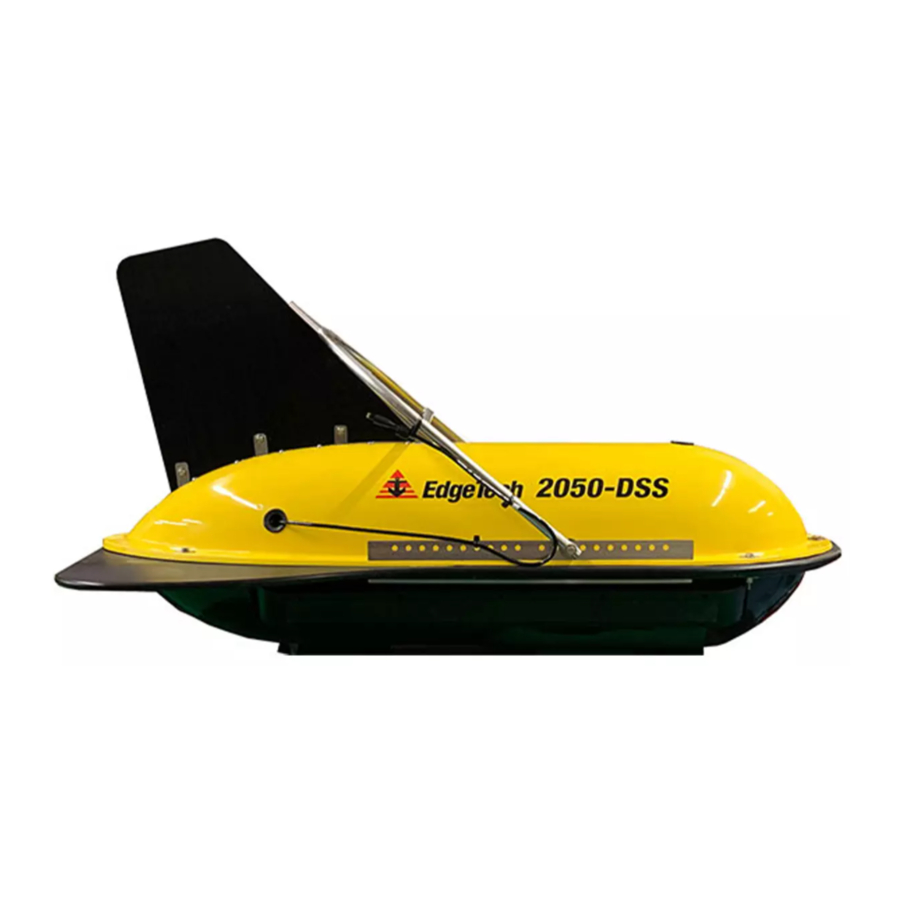
Page 20: Figure 1-2: 2050-Dss Towfish Side View
Figure 1-2: 2050-DSS Towfish Side View Figure 1-3: 2050-DSS Towfish Forward View Figure 1-4: 2050-DSS Towfish Aft View... -
Page 21: 2050-Dss Starmux Iv Topside
Figure 1-6: Test Cable 1.4 Optional Equipment 1.4.1 ROV Mounting Kit The 2050-DSS sub-bottom transducers can be mounted to a customer’s ROV. This kit includes the hardware and cabling to do so. 1.4.2 Magnetometer A magnetometer can be specified or supplied from several manufacturers with EdgeTech's optional magnetometer interface. -
Page 22: Usbl Responder Beacon
Figure 1-7: 2050-DSS Magnetometer Interface 1.4.3 USBL Responder Beacon An ultra-short baseline (USBL) beacon provides underwater acoustic positioning of the 2050-DSS Towfish. USBL N Edgetech does offer USBL products that can be found on the AVIGATION AND OSITIONING SECTION our website. Consult your Edgetech Sales Representative or... -
Page 23: Specifications
2.0 SPECIFICATIONS Specifications for the 2050-DSS Side Scan and Sub-Bottom System Components are provided in the subsections to follow. 2.1 2050-DSS Tow Vehicle Specifications 2.1.1 2050-DSS Towfish Physical Specifications SPECIFICATION VALUES Size LxWxH: 149 cm x 78.7 cm x 83.8 cm (58.7 in x 31 in x 33 in) -
Page 24: 2050-Dss Sonar Specifications
850 kHz: 1 cm 850 kHz: 1 cm Sub-Bottom 2-16 kHz 2-16 kHz Frequency: Sub-Bottom 6-10 cm 6-10 cm Resolution Receiver PVDF PVDF Penetration Through 6 meters 6 meters Coarse Sand Penetration Through 80 meters 80 meters Clay Table 2-2: 2050-DSS Sonar Specifications... -
Page 25: Starmux Iv Topside Specifications
High impact industrial trackball (1) Ethernet (3) Ethernet (1) TTL Trigger Input (Sync) (4) RS-232 I/O ports (4) USB 2 (4) USB 3 (1) TTL Trigger Input (Sync) Table 2-3: Starmux IV Specifications 2050-DSS Side Scan and Sub-Bottom System 0024048_REV_A... -
Page 26: Tow Cable Specifications
2.3.1 Armored Tow Cable Specifications EdgeTech currently offers three types of armored tow cables for use with the 2050-DSS system. Contact for further details and options. USTOMER... -
Page 27: Table 2-6: Armored Cable A320327 Specifications
42.7 kN (9,600 lbf) Maximum Working Load 17.1 kN (3.844 ldf) Minimum Bend Radius 18 cm (7.1 in.) Voltage Rating 1200 VDC DC Loop Resistance 33.5 Ω/km (10.2 Ω/kft) Table 2-6: Armored Cable A320327 Specifications 2050-DSS Side Scan and Sub-Bottom System 0024048_REV_A... -
Page 28: 2050-Dss Mechanical Drawings
2-11 2.4 2050-DSS Mechanical Drawings 2.4.1 2050-DSS Towfish Mechanical Drawing Figure 2-1: 2050-DSS Towfish Drawing (0023737)-Click Image For Embedded PDF... -
Page 29: 2050-Dss Electronic Bottle And End Cap Configuration Drawing
2.4.2 2050-DSS Electronic Bottle and End Cap Configuration Drawing Figure 2-2: 2050-DSS Electronics Bottle Drawing (0023404) -
Page 30: 2050-Dss Sub Bottom Transducer Drawing
2-13 2.4.3 2050-DSS Sub Bottom Transducer Drawing Figure 2-3: 2050-DSS KT-216D Transducer Drawing (0012552)-Click Image for Embedded PDF... -
Page 31: 2050-Dss Pvdf Hydrophone Drawing
2.4.4 2050-DSS PVDF Hydrophone Drawing Figure 2-4: 2050-DSS Hydrophone PVDF Drawing (0017353)-Click Image for Embedded PDF... -
Page 32: 2050-Dss Side Scan Transducer Drawing
2-15 2.4.5 2050-DSS Side Scan Transducer Drawing Figure 2-5: 2050-DSS Side Scan Array Drawing (0019213) -
Page 33: 2050-Dss Test Cable Drawing
2.4.6 2050-DSS Test Cable Drawing Figure 2-6: Test Cable (0011690) -
Page 34: 2050-Dss Starmux Iv Topside Digital Link Drawings
2-17 2.4.7 2050-DSS Starmux IV Topside Digital Link Drawings Figure 2-7: Starmux IV ICD (0022246)- Click Image For Embedded PDF... -
Page 35: Figure 2-8: 2050-Dss Rack Mounted Option
Figure 2-8: 2050-DSS Rack Mounted Option... -
Page 36: Technical Description
Diagrams and labeled photographs are provided. 3.1 2050-DSS Tow Vehicle Technical Description The 2050-DSS Tow Vehicle is designed to support a default configuration of one vertically oriented sub- bottom transducer, a PVDF sub-bottom receiver, port and starboard side scan sonar transducer arrays, and an internal sonar processor. -
Page 37: 2050-Dss Towfish System Diagram
3-20 3.1.1 2050-DSS Towfish System Diagram Figure 3-2: 2050-DSS Towfish System Diagram 2050-DSS SIDE SCAN AND SUB-BOTTOM SYSTEM 0024048_REV_A... -
Page 38: 2050-Dss Sonar Processor Diagram
3-21 3.1.2 2050-DSS Sonar Processor Diagram Figure 3-3: 2050-DSS Sonar Processor Diagram (0023520) -
Page 39: 2050-Dss Sonar Processor Endcap Diagram
3-22 3.1.3 2050-DSS Sonar Processor Endcap Diagram Figure 3-4: Sonar Processor Endcap Diagram (0023521) 2050-DSS SIDE SCAN AND SUB-BOTTOM SYSTEM 0024048_REV_A... -
Page 40: 2050-Dss Main I/O Interface (J1)
The 2050 Tow fish Electronics Bottle has a TOW/ROV Main I/O connection. The system is designed to run on the standard 375VDC with telemetry powered from a standard EdgeTech topside. The Main I/O also has connections to be powered from an ROV. The Main power is 48VDC. The power required is 150 Watts with the ability to sustain a voltage drop of no more than 5VDC during transmit cycles. -
Page 41: 2050-Dss Magnetometer I/O Interface (J2)
3-24 3.1.5 2050-DSS Magnetometer I/O Interface (J2) The 2050 has an interface for a magnetometer. The bulkhead is wired to the 2050 bottles RS232 serial COM port. The wiring for the bulkhead is listed in the table below. The standard interface cable is 0007367. -
Page 42: 2050-Dss Responder I/O Interface (J8)
4ms. The wiring for the bulkhead is listed in the table below. EdgeTech has options for different cables available for interfacing to various devices. This connector also can be configured using software to be used as an external trigger input or output to sync the sonar system with other devices. -
Page 43: 2050-Dss Starmux Iv Topside Technical Description
3-26 3.2 2050-DSS Starmux IV Topside Technical Description Edgetech topside digital links provide power to the towfish while acting as a digital link between the towfish and a topside computer with EdgeTech’s Discover application installed on it. Discover provides the ability to monitor and control towfish systems and process and record sonar data. The digital link also provides input connections for supporting survey equipment, navigation devices, and a trigger. -
Page 44: Figure 3-7: Starmux Iv Front And Back Panels
3-27 Digital Display Starmux Power Switch Indicator Lights AC Fuse FSK Sync Power Fuse Sea Cable Connector Data Ethernet Port Connector Switch Grounding Line VAC Connector Figure 3-7: Starmux IV Front and Back Panels... -
Page 45: Starmux Iv 2050 Rack Mount Controls, Indicators, And Connections
DB-9 female connector. RS-232 serial port that connects to the navigation COM-1 NAV Connector system. COM-3 Connector DB-9 female connector. General-purpose RS-232 serial port. Table 3-5: Starmux IV Rack Mount Controls, Indicators, and Connections 2050-DSS SIDE SCAN AND SUB-BOTTOM SYSTEM 0024048_REV_A... -
Page 46: Figure 3-8: Labeled Front Panels Of 2050 Rackmount
3-29 Digital Display Starmux Power Switch Indicator Lights CPU Power and Reset DVD/RW Drive USB Connectors Figure 3-8: Labeled Front Panels of 2050 Rackmount... -
Page 47: Figure 3-9: Labeled Rear Picture Of 2050 Rackmount
3-30 Data Ethernet Connector AC Fuse Sea Cable Connector Fuse Power Switch FSK Sync Connector Grounding Video Card Power Switch USB Connectors PC COM-1 PC COM-3 Ethernet Connectors Figure 3-9: Labeled Rear Picture of 2050 Rackmount... -
Page 48: Setup And Activation
4-31 4.0 SETUP AND ACTIVATION EdgeTech designed the 2050-DSS Side Scan and Sub-Bottom System to be easily set up and activated for operation. Instructions for this process are provided in the subsections to follow. 4.1 Unpacking and Inspection Before unpacking the system components, inspect the shipping containers for any damage. Report any damage to the carrier and to EdgeTech. -
Page 49: Change To A Non-Us Power Plug
The Starmux IV Topside digital link and computer are connected by an ethernet cable, as shown in IGURE 4-1. NOTE The ethernet cable must be plugged into the right side ethernet port on the computer and any one of the data ports on the Starmux IV. 2050-DSS SIDE SCAN AND SUB-BOTTOM SYSTEM 0024048_REV_A... -
Page 50: Connecting And Attaching The Tow Cable To The Towfish
4-33 Right Ethernet Port on Computer Figure 4-1: Starmux IV and Computer Connected By Ethernet Cable 4.4.1 Connecting and Attaching the Tow Cable to the Towfish Data Connectors • A tow winch with a slip ring should be used with the tow cable to tow the vehicle. •... -
Page 51: Connecting The Starmux Iv To The Computer
3. Connect the Ethernet patch cable to the DATA 1 Connector of the Starmux IV Digital Link and the computer's ethernet connector. If it is an EdgeTech 2U, connect to the right-side Ethernet Connector. Any Category 5 Ethernet patch cable can be used as long as it doesn’t exceed 100 feet in length. -
Page 52: Connecting To The 2050 Rack Mount With Starmux Iv Dl
3. Verify that an Ethernet patch cable is connected to the DATA 1 Connector of the Starmux IV Digital Link and the computer's ethernet connector. If it is an EdgeTech 2U, it should be connected to the right-side Ethernet Connector. -
Page 53: Navigation Interface
Figure 4-4: Windows Manual IP Properties Window configuring the network interface card IPv4 address on the computer. If you have purchased the topside with an EdgeTech computer, this will be preconfigured. If you are connecting a computer not preconfigured by EdgeTech, you must manually set the IPv4 address of your computer to 192.9.0.nnn, where nnn is any integer from 1 to 100, except for the... -
Page 54: Performing System Pre-Deployment Testing
192.9.0.104-192.9.0.224 IP Range Not Recommended 192.9.0.226-192.9.0.255 Table 4-2: 2050-DSS Factory Installed Component IP Addresses 4.5 Performing System Pre-Deployment Testing It is good practice to test that the subsea processor is active and error-free, followed by a test of each sonar subsystem before deployment. Instructions on how to do so are provided in the manual sections below. -
Page 55: Performing Sub Bottom Pre-Deployment Checks
The Sub-Bottom Display Window is displayed in below, and the IGURE results of a tap test are shown in 4-12. IGURE NOTE: See the 2050-DSS S for detailed ISCOVER OFTWARE ANUAL software information. 2050-DSS SIDE SCAN AND SUB-BOTTOM SYSTEM 0024048_REV_A... -
Page 56: Figure 4-8: Discover 2050 Sub-Bottom Display Window
4-39 Figure 4-8: Discover 2050 Sub-Bottom Display Window To perform the pre-deployment checks: 1. Follow the instructions in section of this manual and activate the Sub- CTIVATING THE OPSIDE Bottom amplifiers in Web Relay. 4-9. 2. Run a Tap Test – Navigate to the Sub-Bottom Control Tab, shown in IGURE Figure 4-9: The Sub-Bottom Control Tab 3. -
Page 57: Figure 4-10: Sub-Bottom Control Tab-Pulse And Transmit Level Called Out
6. Tap the underside of the tow vehicle near the PVDF receiver with the handle of a screwdriver while observing the Sub-Bottom Waterfall Display in Discover. Streaks or noise spikes should be visible in the Waterfall Display, as shown in 4-12. This IGURE verifies the receive channel is operating. 2050-DSS SIDE SCAN AND SUB-BOTTOM SYSTEM 0024048_REV_A... -
Page 58: Sbg Ahrs Usage
The introduction of the 2050-DSS has given us an opportunity to improve the heading sensor's performance by fitting a MEMS-based inertial motion sensor unit that combines data from a built-in gyroscope, accelerometer, and magnetic field sensors using a Kalman filter. -
Page 59: Tow Vehicle Bridle Removal, Adjustment, And Installation
4.7 Tow Vehicle Bridle Removal, Adjustment, and Installation The 2050-DSS is delivered with a tow bridle that provides for towing the vehicle with an armored tow cable behind a vessel. The tow bridle can be tilted forward, back, or removed for shipping in storage. It is delivered in a default position that provides a flat and stable tow in typical tow conditions. -
Page 60: Figure 4-13: 2050-Dss Starboard Bridle Power And Data Cable Cable-Tie Locations
[3] Cable Ties Figure 4-13: 2050-DSS Starboard Bridle Power and Data Cable Cable-Tie Locations 2. Remove the [2] split rings using needle nose plyers. 3. Unthread the [2] 3/8” hex nuts, [2] 3/8” bolts, [4] 3/8” standard washers, and [2] 3/8” fender flat washers using the 9/16 Wrenches. -
Page 61: Tow Bridle Adjustment
4.7.3 Tow Bridle Installation The tow bridle is attached to the 2050-DSS Vehicle with two Bolt, washer, nut, and split ring hardware sets on the port and starboard side of the vehicle. The tow vehicle's power and data cable also runs up the starboard side of the vehicle and bridle arm and is lashed to the arm and rail with cable ties. -
Page 62: Figure 4-15: Tow Fish Bridle Mounting Bracket Positioning
• • [2] 1-16” Split Rings Table 4-4: 2050-DSS Tow Bridle Installation Tools and Hardware Instructions: 1. Position the detached bridle so that both ends are outside the port and starboard mounting rails at the same point. The default position in 7-8 mounting rail holes from the forward end of the vehicle. -
Page 63: Figure 4-16: Tow Bridle Arm Removal Hardware
Leave enough slack in the cable between the bridle and horizontal support cable ties to rotate the tow arm and never pull on the cable. [3] Cable Ties Figure 4-17: 2050-DSS Starboard Bridle Power and Data Cable Cable-Tie Locations 2050-DSS SIDE SCAN AND SUB-BOTTOM SYSTEM 0024048_REV_A... -
Page 64: Towfish Deployment
4-47 4.8 Towfish Deployment The 2050-DSS is ruggedly built, but care is needed to deploy the system and get the best survey results. This involves carefully lowering it to an ideal survey depth, utilizing and monitoring the Discover Bottom Tracking feature to avoid striking the bottom, and carefully recovering and disconnecting the towfish when the survey is completed. - Page 65 OWFISH AYBACK HARTS NOTE: For detailed information about the Discover software, including recording data, refer to the 2050-DSS S ISCOVER OFTWARE ANUAL 2050-DSS SIDE SCAN AND SUB-BOTTOM SYSTEM 0024048_REV_A...
-
Page 66: Figure 4-19: 2050-Dss Towfish Deployment
4-49 Figure 4-19: 2050-DSS Towfish Deployment 1. With the survey vessel underway at up to two knots, slowly and carefully lower the towfish into the water, well away from the propeller. Do not let the Towfish strike the hull of the survey vessel. -
Page 67: Towfish Layback Charts
The results listed in these tables are calculated using the Woods Hole WHOI cable program with best-estimated parameters for vehicle weight and buoyancy and cable weight and stiffness. EdgeTech disclaims any liability for consequential damage resulting from using the data in the tables. -
Page 68: Cable A320327 Layback Chart
4-51 4.9.1 Cable A320327 Layback Chart 2050-DSS WITH CABLE A320327 (MAX. WORKING LOAD = 17.1 KN) Max Cable Cable Paid Out (m) Speed (kts) Speed (m/s) Depth Achieved (m) Tension (N) 2.00 1.03 2,065 4.00 2.06 1,873 6.00 3.09 2,117 8.00... -
Page 69: Cable A302799 Layback Chart
4-52 4.9.2 Cable A302799 Layback Chart 2050-DSS WITH CABLE A302799 (MAX. WORKING LOAD = 17.8 KN) Cable Paid Out (m) Speed (kts) Speed (m/s) Depth Achieved (m) Max Cable Tension (N) 2.00 1.03 2,605 4.00 2.06 2,841 6.00 3.09 4,133 8.00... -
Page 70: Cable A309183 Layback Chart
4-53 4.9.3 Cable A309183 Layback Chart 2050-DSS WITH CABLE A309183 (MAX. WORKING LOAD = 44.0 KN) Cable Paid Out (m) Speed (kts) Speed (m/s) Depth Achieved (m) Max Cable Tension (N) 2.00 1.03 4,551 4.00 2.06 4,393 6.00 3.09 6,044 8.00... -
Page 71: Maintenance
5-54 5.0 MAINTENANCE The 2050-DSS Side Scan and Sub-Bottom System is ruggedly designed and built and therefore requires little maintenance. However, to ensure long-lasting, reliable service, some periodic maintenance is recommended. Maintenance on the system should be performed regularly. Most of the maintenance is performed after each deployment and recovery cycle. -
Page 72: Figure 5-1: 2050-Dss Tail Rudder [3] Bolt Hardware Assembly Locations
5-55 [3] Tail Rudder Mounting Assemblies Figure 5-1: 2050-DSS Tail Rudder [3] Bolt Hardware Assembly Locations REQUIRED TOOLS AND HARDWARE Hardware: Tools: 1/2” Crescent or Adjustable Wrench • [3] 5/16” Bolts • [3] 5/16” Nuts • 1/2” Crescent, Adjustable Wrench of Socket •... -
Page 73: Figure 5-2: Tail Rudder Bolt Hardware
Tighten until snug. Tail Rudder [6] 5/16” Washers [3] 5/16” Hex Nut [3] 5/16” Bolt Tail Rudder Mounting Bracket Figure 5-2: Tail Rudder Bolt Hardware Figure 5-3: Tail Rudder Bolt Hardware Disassembly 2050-DSS SIDE SCAN AND SUB-BOTTOM SYSTEM 0024048_REV_A... -
Page 74: Storage
5-57 5.4 Storage When not in use, all the 2050-DSS system components should be packed in their original shipping containers, in the same way they were originally shipped and stored in a dry area. 5.5 Opening the 2050-DSS Towfish The procedures below describe how to open the 2050-DSS Tow Vehicle. -
Page 75: Figure 5-5: 2050-Dss Bolt Hardware Disassembly
3/8” Hex Nut the [2] threaded tow plates securing the tow Figure 5-6: 2050-DSS Bolt Hardware Assembly bridle mounting rails and upper and lower- shells using the 9/16” wrenches. 4. Remove the [2] tow bridle mounting rails from the vehicle. -
Page 76: Sonar Processor Removal And Installation
The horizontally mounted sonar processor can be removed by opening the top cover of the tow vehicle, disconnecting the cabling, removing the two bottle clamps by unthreading the four hex bolt assemblies securing it, and lifting the processor bottle out of the tow vehicle. [4] Bolt Hardware Assemblies Figure 5-7: 2050-DSS Sonar Processor Mounting Assembly... -
Page 77: Table 5-3: Sonar Processor Installation And Removal Tools And Hardware
Always connect the tow cable to the tow vehicle first. Sonar Processor Removal Instructions 1. Power down the 2050-DSS system and disconnect the tow vehicle power and data cable. 2. Remove tow vehicle’s upper-shell. See the 2050-DSS T... -
Page 78: Sub-Bottom Transducer Removal And Installation
Starmux IV. Injury or death can occur if the exposed connector on the tow cable is energized. Always connect the tow cable to the towfish first. Removal Instructions: 1. Power down the 2050-DSS system and disconnect the tow vehicle power and data cable. 2. Remove towfish upper-shell. See the 2050-DSS T... -
Page 79: Operating System Restoration
3. Plug the cable back into the sub- bottom transducer or endcap. Figure 5-9: 2050-DSS Sub Bottom Transducer Clamp and Mount Orientations 5.8 Operating System Restoration The following section outlines the procedures for backing up and restoring the system drive. - Page 80 5-63 4. Under Please select boot device: By using up/down arrow keys, select EUFI: Corsair Voyager 3.0 000A, then press Enter. 5. Wait for Paragon Backup & Recovery 14 Home screen to appear, then click the Restore icon. 6. On Welcome to the Restore Wizard screen, click Next. 7.
-
Page 81: Troubleshooting
Starmux IV continues to flash Modem settings on the digital Contact CUSTOMER SERVICE after several minutes, and no link are incorrect. LINK is established. Check the unit using a different Towfish is faulty. towfish. 2050-DSS Side Scan and Sub-Bottom System 0024048_REV_A... -
Page 82: Table 6-1: Starmux Iv Troubleshooting Table
6-65 SYMPTOM PROBABLE CAUSE CORRECTIVE ACTION Check the LAN cable LAN cable disconnected. connection. Check the tow cable Tow cable disconnected. connection. Please contact CUSTOMER Modem settings are incorrect. SERVICE for modem settings. Check all connections to the The modem is disconnected modem are correct per the The DISCOVER survey software internally to the digital link. -
Page 83: Table 6-2: 2050-Dss Accessory Kit
0019478 LABEL SHEET WHITE MAILING 04 INCH 1.33 INCH / 14 0023928 DOC TEMPLATE 2050 DSS TOW FISH CONSUMABLES KIT LABEL SET 0008083 ASSY SUB CABLE 4200 VGA Table 6-2: 2050-DSS Accessory Kit 2050-DSS Side Scan and Sub-Bottom System 0024048_REV_A...
Need help?
Do you have a question about the 2050-DSS and is the answer not in the manual?
Questions and answers