
Related Manuals for Edgetech 3200-XS


Summary of Contents for Edgetech 3200-XS
- Page 1 3200-XS SUB-BOTTOM SYSTEM U S E R H A R D W A R E M A N U A L 0004840_REV_E 7/2/2018 EdgeTech 4 Little Brook Road West Wareham, MA 02576 Tel: (508) 291-0057 Fax: (508) 291-2491 www.EdgeTech.com...
- Page 2 The information, figures, and specifications in this manual are proprietary and are issued in strict confidence on condition that they not be copied, reprinted, or disclosed to a third party, either wholly or in part, without the prior, written consent of EdgeTech. Any reproduction of EdgeTech supplied software or file sharing is strictly prohibited.
-
Page 3: Attention - Read This First
ATTENTION – READ THIS FIRST! All personnel involved with the installation, operation, or maintenance of the equipment described in this manual should read and understand the warnings and cautions provided below. CAUTION! This equipment contains devices that are extremely sensitive to static electricity. -
Page 4: Hardware Variations And Compatibility
EdgeTech will make every effort to see that replacement components are interchangeable and use the same software drivers (if applicable). At times, however, direct replacements may not exist. When this happens, EdgeTech will provide the necessary drivers with the replacement part, if applicable. -
Page 5: About This Document
Purpose of this Manual The purpose of this manual is to provide the user with information on the setup and use of EdgeTech’s 3200-XS. Although this manual encompasses the latest operational features of the 3200-XS, some features may be periodically upgraded. -
Page 6: Warranty Statement
All equipment manufactured by EdgeTech is warranted against defective components and workmanship for a period of one year after shipment. Warranty repair will be done by EdgeTech free of charge. Shipping costs are to be borne by the customer. Malfunction due to improper use is not covered in the warranty, and EdgeTech disclaims any liability for consequential damage resulting from defects in the performance of the equipment. -
Page 7: Software Service Overview
Software Updates and Enhancements EdgeTech customers can download new software releases with all modifications and enhancements from the EdgeTech ftp site. Major software issues, should they occur, will be reported directly to the customer. New software releases consist of the following: •... -
Page 8: Returned Material Authorization
Refer to RMA number on all documentation and correspondences. All returned materials must be shipped prepaid. Freight collect shipments will not be accepted. All equipment should be adequately insured for shipping, but equipment belonging to EdgeTech must be insured for full value. - Page 9 CUSTOMER SERVICE Customer service personnel at EdgeTech are always eager to hear from users of our products. Your feedback is welcome, and is a valuable source of information which we use to continually improve these products. Therefore we encourage you to contact EdgeTech Customer Service to offer any suggestions or...
-
Page 10: Company Background
— for the acquisition of underwater data, including marine, estuarine, and coastal applications — for over 50 years. EdgeTech responds to the needs of the Scientific, Naval, and Offshore communities by providing industry- leading equipment — such as Sub-Bottom Profilers, Side Scan Sonar, Acoustic Releases, USBL Positioning Systems, and Bathymetric Systems —... -
Page 11: Table Of Contents
TABLE OF CONTENTS ATTENTION – READ THIS FIRST! .................... iii Warnings, Cautions, and Notes ........................ iii HARDWARE VARIATIONS AND COMPATIBILITY ..............iv ABOUT THIS DOCUMENT ....................... v Purpose of this Manual ..........................v Liability ..............................v Revision History ............................v WARRANTY STATEMENT ...................... - Page 12 1.3.3 Tow Cable ..........................1-8 2.0: SPECIFICATIONS ......................2-1 2.1 3200 Rack Mount Processor ......................2-1 2.1.1 Rack Mount General Specifications ..................2-1 2.1.2 Processor Unit Specs......................2-2 2.1.3 Power Amplifier ........................2-2 2.1.3.1 Power Output ......................... 2-2 2.1.3.2 Performance ........................2-3 2.1.3.3 Construction ........................
- Page 13 4.0: MAINTENANCE ......................4-1 4.1 Periodic Maintenance ........................4-1 4.1.1 Cleaning the 3200-XS Topside Processor ................4-1 4.1.2 Cleaning the Tow Vehicle and Tow Cable after Use ............. 4-1 4.1.3 Inspecting and Cleaning the Underwater Connectors ............4-1 4.1.4 Storage ..........................
-
Page 14: List Of Figures
LIST OF FIGURES Figure 1-1: 3200 Rack Mount Processor ....................1-5 Figure 1-2: Tiger and Mother Boards inside 3200-XS Topside Processor ..........1-6 Figure 1-3: SB-424, SB-216S, and SB-512i Tow Vehicles ................1-7 Figure 1-4: 75-Meter Kevlar Reinforced Tow Cable ................... 1-8 Figure 2-1: Tiger Board Set: Carrier (Front view) –... - Page 15 Figure 4-7: SB-424, SB-216S and SB-512i Tow Vehicle Internals ............... 4-6 Figure 5-1: SEA CABLE Connector—Female Face View ................5-4 Figure 5-2: Male Marshal Connector – 86-5MC (Tow Vehicle to Tow Cable Connection) ......5-5 Figure 5-3: Female Marshal Connector – 86-5FC (Tow Cable to Tow Vehicle Connection) ...... 5-5 Figure 5-4: Wiring Harness, Rack Mount Deck Unit –...
- Page 16 LIST OF TABLES Table 2-1: Rack Mount General Specifications ..................2-1 Table 2-2: 3200-XS Topside Processor Specs ..................... 2-2 Table 2-3: Power Amplifier Specs: Power Output ..................2-2 Table 2-4: Power Amplifier Specs: Performance ..................2-3 Table 2-5: Power Amplifier Specs: Construction ..................2-3 Table 2-6: Tow Vehicle Specifications ......................
-
Page 17: Overview
EdgeTech’s proprietary Full Spectrum CHIRP technology to generate cross- sectional images of the seabed and collect digital normal incidence reflection data over many frequency ranges. The 3200-XS transmits an FM pulse (also called "CHIRP pulse") that is linearly swept over a full spectrum frequency range. -
Page 18: High Repeatability
EdgeTech technical support can provide assistance in selecting the best tow vehicle for your application. -
Page 19: Gaussian Shaped Amplitude Spectrum Outgoing Pulse
2–10 kHz signal, for example is 20 degrees measured at the -3db points. 1.2 Full Spectrum CHIRP Technology Applications Applications of Full Spectrum CHIRP Technology used in the 3200-XS Sub-Bottom Profiling System include: • EEZ resource development •... -
Page 20: Main System Components
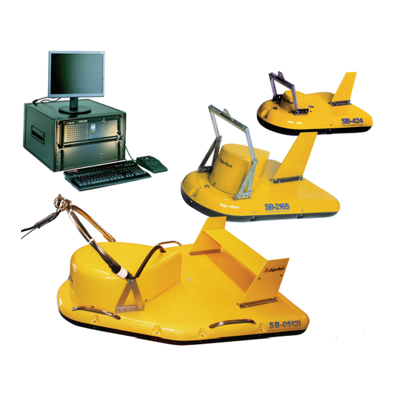
• Environmental site investigations 1.3 Main System Components The 3200-XS Sub-Bottom Profiling System is composed of three main components: a 3200 Rack Mount Processor; an SB-424, SB-216S or SB-512i Tow Vehicle; and a Tow Cable. 1.3.1 3200 Rack Mount Processor... -
Page 21: Figure 1-1: 3200 Rack Mount Processor
The 3200 Rack Mount processor also includes the EdgeTech DISCOVER 3200SB software preinstalled on the 3200-XS Topside Processor. DISCOVER 3200SB is a data acquisition and processing program designed exclusively for EdgeTech Full Spectrum CHIRP sonar systems. The program, which runs on the Microsoft Windows 7 operating system, verifies that the sonar system is working properly prior to deployment by providing data displays, diagnostics, data recording, playback, and printer outputs. -
Page 22: Sb-424, Sb-216S, And Sb-512I Tow Vehicles
Tiger Board Mother Board Power Supply Figure 1-2: Tiger and Mother Boards inside 3200-XS Topside Processor 1.3.2 SB-424, SB-216S, and SB-512i Tow Vehicles The SB-424, SB-216S, and SB-512i Tow Vehicles are each designed to operate over a specific frequency range, and as lower operating frequencies generally require longer hydrophone arrays and larger transducers, the vehicles differ primarily in size and weight. -
Page 23: Figure 1-3: Sb-424, Sb-216S, And Sb-512I Tow Vehicles
SB-424 Tow Vehicle SB-216S Tow Vehicle SB-512i Tow Vehicle Figure 1-3: SB-424, SB-216S, and SB-512i Tow Vehicles... -
Page 24: Tow Cable
1.3.3 Tow Cable The 3200-XS does not come standard with a specific type of cable, but requires one to operate, and must be specified at the time of purchase. EdgeTech has multiple lengths and cable material types available. The maximum cable length available for the 3200-XS system is 600 Meters. Contact USTOMER for more information. -
Page 25: Specifications
The Deck Unit is application specific. It should not be used for purposes other than that for which it was intended. 2.1.1 Rack Mount General Specifications The general specifications for the 3200-XS Rack Mount Processor are shown in 2-1. ABLE... -
Page 26: Processor Unit Specs
Acoustic power 212 dB re1 NPa @ 1 meter peak (approx.) at center frequency Input voltage 120-220 VAC, 50/60 Hz, auto sense Table 2-2: 3200-XS Topside Processor Specs 2.1.3 Power Amplifier The specifications for the Power Amplifier are show in 2-5, 2-4, and 2-5. -
Page 27: Performance
2.1.3.2 Performance SPECIFICATION VALUE Frequency Response (at 1 watt, 20 Hz – 20 kHz ± 0.25 dB into 8 ohms) Signal to Noise Ratio (below rated full bandwidth > 108 dB power, A-weighted) Total Harmonic Distortion (THD) (at 1 watt into 8 ohms) <... -
Page 28: Carrier Board
2.0 SPECIFICATIONS The Tiger board was designed to support a combined sonar system (with both sub-bottom as well as multi- frequency side-scan capability), or to be used single channel as a basic sub-bottom controller. At periodic intervals, the board generates the transmit waveform(s), and it continuously buffers ADC data. The Tiger board represents a new generation of re-engineered and optimized sonar electronics. -
Page 29: Figure 2-1: Tiger Board Set: Carrier (Front View) – 0006013
Figure 2-1: Tiger Board Set: Carrier (Front view) – 0006013 Figure 2-2: Tiger Board Set: Carrier (Rear View) – 0006013... -
Page 30: Sb-424, Sb-216S, And Sb-512I Tow Vehicles
2.0 SPECIFICATIONS Figure 2-3: Tiger Board Set: Acquisition PCB - 0014231 Figure 2-4: Tiger Board Set: SIBU aka Sonar Interface Board – 0011637 2.1.5 SB-424, SB-216S, and SB-512i Tow Vehicles The general specifications for the SB-424, SB-216S, and SB512i Tow Vehicles are show in 2-6. -
Page 31: Table 2-6: Tow Vehicle Specifications
SPECIFICATION SB-424 VALUE SB-216S VALUE SB-512i VALUE Frequency range 4-24 kHz 2-16 kHz 0.5-12 kHz Pulse type FM & WB (wide band) 0.5-8.0 kHz/5 ms FM 0.5-2.7 kHz/40 ms WB 0.5-6.0 kHz/20 ms WB 4-24 kHz/10 ms 2-15 kHz/20 ms 0.5-4.5 kHz/50 ms FM Pulse bandwidth/pulse 4-20 kHz/10 ms... -
Page 32: Mechanical Drawings
2.0 SPECIFICATIONS a. Vertical resolution is the smallest distinguishable distance between the peaks of two reflections that can be displayed on the screen as separate reflectors. Sound energy is reflected back to the sonar system when the transmitted pulse encounters a change in density. The resolution of a sonar system is measured by its ability to distinguish between two adjacent targets. -
Page 33: Figure 2-5: Sb-216 Towfish Outline Drawing
Figure 2-5: SB-216 Towfish Outline Drawing... -
Page 34: Figure 2-6: Sb-424 Towfish Outline Drawing
2-10 Figure 2-6: SB-424 Towfish Outline Drawing... -
Page 35: Figure 2-7: Sb-512I Towfish Outline Drawing
2-11 Figure 2-7: SB-512i Towfish Outline Drawing... -
Page 36: Kevlar Reinforced Tow Cable Specifications
2.2.1 Kevlar Reinforced Tow Cable Specifications 2-7. The 75meter length The general specifications for the Kevlar Reinforced Tow Cable are shown in ABLE is not the only cable option for the 3200-XS system, but it is the most popular. SPECIFICATION VALUE (1) #16 AWG... -
Page 37: Setup And Activation
. Do not install or operate any equipment that appears to be damaged. USTOMER ERVICE Although the items shipped may vary, depending on the customer requirements, the 3200-XS Sub-Bottom Profiling System typically includes the following: • Topside Unit and Monitor •... -
Page 38: Power Requirements
3.0: SETUP AND ACTIVATION 3.2 Power Requirements The 3200-XS requires a 120–220 VAC, 50/60 Hz (<1500 watts). The input voltage is auto sensing for the topside, and the power amplifier makes use of a universal power input. 3.2.1 Use of an Uninterruptable Power Supply The AC power source should be continuously free of high amplitude and high frequency transients. -
Page 39: Rack Mount Controls And Indicators
Secure the rack mount topside in place, using tie-downs if necessary, near the required AC power source. If you are mounting the 3200-XS Topside Processor and the Power Amplifier in a 19-inch rack other than the supplied rack mount enclosure, ensure that there is ample room behind the rack for connecting the cables. -
Page 40: Figure 3-1: Front Panel Of 3200-Xs Rack Mount Topside
Removable 1-TB HDD System Indicator System Power DVD R/RW Drive Hard Disk Hard Disk Indicator Reset Button Connectors Ready Indicators Figure 3-1: Front Panel of 3200-XS Rack Mount Topside CH1 Dial Power, Bridge, & CH2 Dial (defunct) Data Indicators (defunct) -
Page 41: Figure 3-2: Topside Rear Panel Controls And Connections
TRIGGER IN TRIGGER OUT COM 1-NAV COM 3 Ethernet1 Ethernet2 Connector Connector Connector Connector Connectors Connectors Mini Display Port Video Connectors Sonar Data Main I/O Connector POWER AMP OUT TX1 indicator Power Supply POWER AMP OUT USB3 Ports USB 3.1 Ports TX2 indicator 12 VDC OUT TO PREAMP test point... -
Page 42: Rack Mount Deck Unit Connections
(2) USB3 (2) USB3.1 AC POWER: CEE-type AC input and output connectors. AC input connector connects to AC power source, and AC output connectors are available for powering the LCD monitor and other equipment if required. 3200-XS SUB-BOTTOM SYSTEM 0004840_REV_E... -
Page 43: Connecting The System Components
3.6 Connecting the System Components All of the 3200-XS Sub-Bottom Profiling System components, including optional components, such as a printer, a navigation system, and external sonar systems, are made to the Rack Mount processor. WARNING! Do not connect the tow cable to the Rack Mount before connecting it to the tow vehicle, otherwise injury or death can occur if the exposed connector on the tow cable is energized. -
Page 44: Figure 3-3: Reinforced Cable Attached To Sb-216S Tow Vehicle
3.0: SETUP AND ACTIVATION Figure 3-3: Reinforced Cable Attached to SB-216S Tow Vehicle Tow Cable Figure 3-4: Recommended Method for Dressing and Strain Relieving Tow Cable 3200-XS SUB-BOTTOM SYSTEM 0004840_REV_E... -
Page 45: Connecting The Rack Mount Topside
7. If a navigation system is to be used, connect the navigation system output to the COM 1-NAV connector. 8. If an external source is to be used to trigger the 3200-XS Sub-Bottom Profiling System, connect the trigger output of this source to the TRIGGER IN connector. -
Page 46: Pre-Deployment Tests
3-5. An example Tap Test is shown in 3-9. IGURE IGURE NOTE: See EdgeTech DISCOVER Sub-Bottom software manual, 0019800, for additional software information. Based on default installation, DISCOVER and SONAR.EXE start automatically. Figure 3-5: The DISCOVER Sub-Bottom Main Window 3200-XS SUB-BOTTOM SYSTEM... -
Page 47: Figure 3-6: Successful Self-Test
3-11 To perform the pre-deployment checks: 1. Follow the instructions in CTIVATING THE SYSTEM 2. SONAR.EXE runs a self-test, with an audible chirp, indicating the test passed. A successful test is shown in 3-6. IGURE a. If the test fails, the SONAR.EXE window will remain on the desktop, and the failure mode will be described in the window. -
Page 48: Figure 3-9: Tap Test
Waterfall Display in the DISCOVER window. Streaks or noise spikes should be visible in the Waterfall Display, as shown in 3-9. This verifies the receive channel is IGURE operating. Figure 3-9: Tap Test 3200-XS SUB-BOTTOM SYSTEM 0004840_REV_E... -
Page 49: Tow Vehicle Deployment
The SB-424, SB-216S, and SB-512i Tow Vehicles can be towed using a Kevlar Reinforced Tow Cable that is available separately with the 3200-XS Sub-Bottom Profiling System. However, for the larger SB-0512i tow cable, a steel cable with a minimum 500 Kg (1100 lb.) working strength is recommended instead. -
Page 50: Conducting Sediment Classification Surveys When Towing
Refer to the “DISCOVER Sub-Bottom Software User’s Manual” for details. For sediment classification, the tow fish pulses must be calibrated by the end user. Contact to obtain the calibration procedure. USTOMER ERVICE 3200-XS SUB-BOTTOM SYSTEM 0004840_REV_E... -
Page 51: Maintenance
3200-XS Topside Processor, can be performed as necessary. 4.1.1 Cleaning the 3200-XS Topside Processor The 3200-XS Topside Processor in the Deck Unit Should be cleaned inside periodically using a grounded vacuum cleaner. 4.1.2 Cleaning the Tow Vehicle and Tow Cable after Use After retrieving the tow vehicle from the water, use a hose to wash it down, along with the tow cable, with clean, fresh water. -
Page 52: Storage
4.1.4 Storage When not in use, all the components of the 3200-XS Sub-Bottom Profiling System should be packed in their original shipping containers, in the same manner in which they were originally shipped, and stored in a dry area. -
Page 53: Disassembling A Tow Vehicle
4.2.1 Disassembling a Tow Vehicle To disassemble a sub-bottom tow vehicle: 1. Using the blade of a screw driver, pry out the retaining ring from the locking sleeve as shown in 4-1. IGURE Figure 4-1: Retaining Ring and Locking Sleeve Removed 2. -
Page 54: Figure 4-3: Removing The 7/16-Inch Bolts Securing The Teardrop Cover To The Tow Vehicle
Figure 4-3: Removing the 7/16-Inch Bolts Securing the Teardrop Cover to the Tow Vehicle 4. Remove the teardrop cover as shown in 4-4. IGURE Figure 4-4: Removing the Teardrop Cover 5. Disconnect the spider cable from the components as shown in 4-5. IGURE 3200-XS SUB-BOTTOM SYSTEM 0004840_REV_E... -
Page 55: Reassembling A Tow Vehicle
Figure 4-5: Teardrop Cover Removed 6. Using the socket wrench with the 7/16th-inch socket, remove all of the bolts and nuts securing the front half of the top cover of the tow vehicle body as shown in 4-6. Continue with the IGURE rear half using a 1/2 –inch socket. -
Page 56: Figure 4-7: Sb-424, Sb-216S And Sb-512I Tow Vehicle Internals
(0002804) (0003078 – Port) Spider Array Preamplifier (0011655 – Starboard) Transducer (0003169) SHAMU Transducer (0003149) (0003228) (0005014) Hydrophone Spider Array (0003170) SB-512i Transformer Spider box (0002805) (0003172) Figure 4-7: SB-424, SB-216S and SB-512i Tow Vehicle Internals 3200-XS SUB-BOTTOM SYSTEM 0004840_REV_E... -
Page 57: Troubleshooting
The topside is plugged into an appropriate power source (see OWER EQUIREMENTS • The AC cables inside the Deck Unit are plugged into the 3200-XS Topside Processor and the Power Amplifier and to the AC power outlet • The 3200-XS Topside Processor and the Power Amplifier are switched on... -
Page 58: Rack Mount Deck Unit Troubleshooting
3. Verify rear Panel Power Switch is turned on when processor is turned on Indicator is not operating Open 3200-XS Topside Processor to check indicator and wiring. Open 3200-XS Topside Processor and verify Hard Drive is Amber HARD DISK Operating System does not... -
Page 59: Table 5-1: Rack Mount Troubleshooting
Tow vehicle cable harness Verify all cable harness connectors in tow vehicle are properly connections are loose mated. Measure voltage between 12 VDC OUT TO PREAMP test point and PREAMP COMMON test point on back of Deck Unit. Voltage should be 12 VDC. -
Page 60: Connector Pinouts
EFERENCE SOURCE NOT FOUND 5-3. FUNCTION Transmitter output shield +12 VDC Sea ground Transmitter out 1 Transmitter out 2 Preamplifier output Preamplifier Common Preamplifier Common Table 5-2: SEA CABLE Connector Pinouts Figure 5-1: SEA CABLE Connector—Female Face View 3200-XS SUB-BOTTOM SYSTEM 0004840_REV_E... -
Page 61: Figure 5-2: Male Marshal Connector - 86-5Mc (Tow Vehicle To Tow Cable Connection)
FUNCTION Transmitter out 1 Transmitter out 2 Preamplifier common Preamplifier output +12 VDC Sea ground Table 5-3: Tow Cable Connections Figure 5-2: Male Marshal Connector – 86-5MC (Tow Vehicle to Tow Cable Connection) FUNCTION AMPLIFIER OUTPUT 1 AMPLIFIER OUTPUT 2 PREAMPLIFER COMMON PRE-AMPLIFIER SIGNAL RS-232 DATA... -
Page 62: Wiring And Connector Pinout Drawings
5.3 Wiring and Connector Pinout Drawings The 3200-XS Sub-Bottom Profiling System wiring and connector pinout drawings for the Deck Unit and the SB-424, SB-216S, and SB-512i Tow Vehicles are included in the following pages. For the Deck Unit, a wiring harness diagram and connector pinout information are provided. -
Page 63: Figure 5-4: Wiring Harness, Rack Mount Deck Unit - 0004957
Figure 5-4: Wiring Harness, Rack Mount Deck Unit – 0004957... -
Page 64: Figure 5-5: Wiring Diagram, Spider Box, Sb-424 Tow Vehicle - 0003174
Figure 5-5: Wiring Diagram, Spider Box, SB-424 Tow Vehicle – 0003174... -
Page 65: Figure 5-6: Wiring Diagram, Sb-424 Tow Vehicle - 0016154
Figure 5-6: Wiring Diagram, SB-424 Tow Vehicle – 0016154... -
Page 66: Figure 5-7: Wiring Diagram, Spider Box, Sb-216S Tow Vehicle - 0003173
5-10 Figure 5-7: Wiring Diagram, Spider Box, SB-216S Tow Vehicle – 0003173... -
Page 67: Figure 5-8: Wiring Diagram, Sb-216S Tow Vehicle - 0016153
5-11 Figure 5-8: Wiring Diagram, SB-216S Tow Vehicle – 0016153... -
Page 68: Figure 5-9: Wiring Diagram, Spider Box, Sb-512I Tow Vehicle - 0003172
5-12 Figure 5-9: Wiring Diagram, Spider Box, SB-512i Tow Vehicle - 0003172... -
Page 69: Figure 5-10: Wiring Diagram, Sb-512I Tow Vehicle
5-13 Figure 5-10: Wiring Diagram, SB-512i Tow Vehicle... -
Page 70: Figure 5-11: Wiring Diagram, 75-Meter Kevlar Reinforced Tow Cable - 002980
5-14 Figure 5-11: Wiring Diagram, 75-Meter Kevlar Reinforced Tow Cable – 002980... -
Page 71: Figure 5-12: Wiring Diagram, 200-Meter Kevlar Reinforced Tow Cable - 0011685
5-15 Figure 5-12: Wiring Diagram, 200-Meter Kevlar Reinforced Tow Cable – 0011685... -
Page 73: A.0: System Restore
A.0: SYSTEM RESTORE The following section outlines the procedures for backing up and restoring the system drive. CAUTION! All data will be lost upon restoring the system to factory settings. Be sure to backup all data before preforming the procedure below. 1. -
Page 75: B.0: Faq
USTOMER ERVICE for the wiring recommendation. 3. Can you interface a 3200-XS Sub-Bottom Profiling System to a transmit/receive hull mounted array that is customer supplied? This can be done; however, special engineering and calibration is required for optimum results. EdgeTech can provide these services. In short, the output impedance of the Power Amplifier in the Deck Unit must match the input impedance of the transducer array. - Page 76 B.0: FAQ 7. How do environmental conditions affect performance of the 3200-XS Sub-Bottom Profiling System? There are several environmental factors that affect performance: Geological conditions 3200-XS Sub-Bottom Profiling System operating parameters and listed specifications are greatly affected by the geologic conditions that the acoustic energy transmitted from the tow vehicle encounters.
Need help?
Do you have a question about the 3200-XS and is the answer not in the manual?
Questions and answers