
Related Manuals for Edgetech 3400


Summary of Contents for Edgetech 3400
- Page 1 3400 PORTABLE SUB-BOTTOM SYSTEM U S E R H A R D W A R E M A N U A L 0021270_REV_D 3/23/2021 EdgeTech 4 Little Brook Road West Wareham, MA 02576 Tel: (508) 291-0057 Fax: (508) 291-2491 www.EdgeTech.com...
- Page 2 The information, figures, and specifications in this manual are proprietary. They are issued in strict confidence on condition that they not be copied, reprinted, or disclosed to a third party, either wholly or in part, without the prior written consent of EdgeTech. Any reproduction of EdgeTech supplied software or file sharing is strictly prohibited.
-
Page 3: Attention - Read This First
ATTENTION – READ THIS FIRST! All personnel involved with the installation, operation, or maintenance of the equipment described in this manual should read and understand the warnings and cautions provided below. CAUTION! This equipment contains devices that are extremely sensitive to static electricity. -
Page 4: Hardware Variations And Compatibility
Although the component manufacturers and their models and styles may vary from unit to unit, replacement parts will generally be interchangeable. EdgeTech will make every effort to see that replacement components are interchangeable and use the same software drivers (if applicable). At times, however, direct replacements may not exist. When this happens, EdgeTech will provide the necessary drivers with the replacement part, if applicable. -
Page 5: About This Document
ABOUT THIS DOCUMENT We, the employees at EdgeTech, would like to thank you for purchasing 3400. At EdgeTech, our policy is to provide high-quality, cost-effective products and support services that meet or exceed your requirements. We also strive to deliver them on-time and to look for ways to improve them. We take pride in the products we manufacture and want you to be entirely satisfied with your equipment. -
Page 6: Warranty Statement
All equipment manufactured by EdgeTech is warranted against defective components and workmanship for a period of one year after shipment. Warranty repair will be done by EdgeTech free of charge. Shipping costs are to be borne by the customer. Malfunction due to improper use is not covered in the warranty, and EdgeTech disclaims any liability for consequential damage resulting from defects in the performance of the equipment. -
Page 7: Software Service Overview
EdgeTech customers are entitled to contact to report a difficulty, discuss a USTOMER ERVICE problem, or receive advice on the best way to perform a task. When contacted, EdgeTech Customer Service will do the following: Respond within 24 hours by telephone, facsimile, or e-mail •... -
Page 8: Returned Material Authorization
Refer to the RMA number on all documentation and correspondences. All returned materials must be shipped prepaid. Freight collect shipments will not be accepted. All equipment should be adequately insured for shipping, but equipment belonging to EdgeTech must be insured for full value. -
Page 9: Customer Service
CUSTOMER SERVICE Customer service personnel at EdgeTech are always eager to hear from users of our products. Your feedback is welcome and a valuable source of information that we use to improve these products. Therefore, we encourage you to contact EdgeTech Customer Service to offer any suggestions or to request... -
Page 10: Company Background
— such as Sub-Bottom Profilers, Side Scan Sonar, Acoustic Releases, USBL Positioning Systems, and Bathymetric Systems — that have become standards in the industry. EdgeTech consistently anticipates and responds to future needs with an active Research and Development Program. Current efforts are focused on adopting new cutting-edge acoustic technology. -
Page 11: Table Of Contents
TABLE OF CONTENTS ......................... xi LIST OF FIGURES ..........................xvi LIST OF TABLES ..........................xx OVERVIEW ..........................1-1 Key Features of the 3400 Sub-Bottom Profiling System ............1-1 1.1.1 CHIRP Transmission ......................1-1 1.1.1.1 Advantages of Full Spectrum CHIRP Technology ............1-2 1.1.2... - Page 12 Main System Components ......................1-9 1.3.1 3400 Rack Mounted Topside in Case and Ruggedized Laptop ........... 1-10 1.3.2 3400 Cable .......................... 1-10 1.3.3 3400 Standard Towfish ....................... 1-10 1.3.4 3400 Tow Vehicle Pole Mounting Kit .................. 1-11 1.3.5 3400 Options ........................1-12 1.3.5.1...
- Page 13 3400 Standard Towfish Technical Description ................ 3-26 3.1.1 3400 Standard System Connection Diagram ..............3-27 3.1.2 3400 Standard Towfish Electronics Bottle and End Cap Diagrams ........3-28 3.1.3 3400 Standard Towfish Cable and Connector Diagrams ............ 3-31 3400 Portable Topside Technical Description ................. 3-35 3.2.1...
- Page 14 U-Hinge Tow Bridle Adjustment ................. 4-66 4.1.10.2 U-Hinge Tow Bridle Removal Instructions: ..............4-67 4.1.11 Pole Mounting the 3400 Tow Vehicle ................4-72 4.1.12 Removing the Tow Bridle ....................4-72 4.1.13 Removing Weights ......................4-72 4.1.14 Removing the Rear Elevator ....................4-74 4.1.15 Pole Mount Installation Instructions ..................
- Page 15 5.2.1 Cleaning the 3400 OTS Vehicle After Use ................5-92 Inspecting and Cleaning the Underwater Connectors............. 5-93 Storage ............................. 5-93 Altering the 3400 Towfish Configuration ................5-93 5.5.1 Adjusting or Removing the Rear Elevator ................5-94 5.5.2 Removing the Sonar Processor Bottle ................5-95 TROUBLESHOOTING ......................
-
Page 16: List Of Figures
Figure 2-1: 3400 Towfish ICD (Click Image To Open Attached PDF) ............2-19 Figure 2-2: 3400 Towfish With Pole Mounting Hardware ICD (Click Image To Open Attached PDF) ..2-20 Figure 2-3: 3400 OTS Vehicle ICD (Click Image to Open Attached PDF) ..........2-21 Figure 2-4: 3400 Topside ICD (Click Image To Open Attached PDF) ............ - Page 17 Figure 3-5: 3400 Electronics Bottle Pinouts ..................... 3-30 Figure 3-6: Sub Cable T Splice 3400 SBP Tow Cable to Bottle, Transformer, and Tow Cable ....3-31 Figure 3-7: 3400 SBP 50 Meter Tow Cable Page 1 ................... 3-32 Figure 3-8: 3400 SBP 50 Meter Tow Cable Page 2 ................... 3-33 Figure 3-9: Tow Cable to Tow Fish Pinouts (Wet End) ................
- Page 18 Figure 4-18: Bridle Removal-Elbow Hardware Removal ................4-71 Figure 4-19: 3400 Towfish with Pole Mount Installed, Tow Arms, Weights, and Elevator Removed ..4-72 Figure 4-20: 3400 Pole Mount Instruction-Front Panel Removal With (12) Screws and Eye Bolt Called Out .................................
- Page 19 Figure 5-1: OTS Mounting Flange Recessed Structure................5-92 Figure 5-2: Elevator Hex Screw Positions ....................5-94 Figure 5-3: Electronics Bottle Cotter Pin Removal ................... 5-96 Figure 5-4: Electronic Bottle Latch and Rubber Strip Locations .............. 5-97 Figure 7-1: 3400 OTS Vehicle Spares Kit ....................7-102...
- Page 20 Table 2-9: Amplifier Option Electrical Specifications ................2-17 Table 2-10: 50-Meter Tow Cable Specification ..................2-18 Table 3-1: 3400 Topside Front Panel Indicator Light and Switch Descriptions ........3-35 Table 3-2: 3400 Topside Back Panel Switches and Connections ............. 3-36 Table 3-3: Amplifier Front Panel Controls and Indicator Lights ...............
-
Page 21: Overview
EdgeTech’s Discover 3400 sub-bottom acquisition and processing software. The standard 3400 hydrodynamic towfish can either be towed behind a vessel or pole-mounted over the vessel's side. More specialized Over-The-Side (OTS) vehicle variants are available to support greater stability and different transducer options. -
Page 22: Advantages Of Full Spectrum Chirp Technology
All these advantages are discussed in detail below. Separate Acoustic Projectors and Receivers The 3400 Sub-Bottom Profiling System uses acoustic projectors and receivers mounted in a towed vehicle to transmit and receive acoustic FM pulse signals. The projectors are wideband piston-type transducers, and the receivers are hydrophone arrays composed of polyvinylidene difluoride (PVDF) hydrophones. - Page 23 Additional Processing Gain EdgeTech CHIRP technology achieves a signal processing gain over the background noise. This gain is approximately ten times the log of the time-bandwidth product. This improvement is due to the signal having a time duration longer than the inverse of the bandwidth, thus increasing signal energy without increasing the power of the outgoing pulse.
-
Page 24: Dual Wideband Transmitters
1.1.2 Dual Wideband Transmitters The EdgeTech 3400 comes standard in a dual 2-16 kHz transducer configuration that provides an increased source level and beam pattern. Sub-Bottom Transducers Figure 1-1: 3400 Sub-Bottom Transducers 1.1.3 Dual Frequency Transmission Dual alternating pulse technology allows users to transmit two different sub-bottom pulses over the same survey line in a single pass. -
Page 25: Enhanced Sub-Bottom Multi-Channel Pvdf Receiver
1.1.4 Enhanced Sub-Bottom Multi-Channel PVDF Receiver EdgeTech’s PVDF receivers have advantages over other systems. The segmented arrays provide different modes of operation from sub-bottom profiling to very specific applications like Pipeliner Mode. The receivers provide greater sensitivity, a better beam pattern with sidelobes, greater spatial acoustic rejection over other receivers. -
Page 26: Figure 1-5: 3400 Pvdf Imagery Side Lobes With Reduced Echoes
Figure 1-5: 3400 PVDF Imagery Side Lobes with Reduced Echoes Figure 1-6: Comparison of 3400 Vs. Traditional Line Arrays Over Same Survey Line 3400 Portable Sub-bottom System 0021270_REV_C... -
Page 27: Reflection Coefficient Calculation
(up to 30 Hz) for better detection and measurement of the shallow buried pipe/cable. The Pipeline Mode feature of the 3400 can also be used to detect boulders, UXO, buried hazards, or other debris for site clearance and route surveys. -
Page 28: Figure 1-7: Pipeliner Mode Diffraction
Higher pipeline position accuracy is achieved by having the sonar close to the seafloor (2-5m). Configuration for Pipeliner mode doesn’t require hardware configuration and is described in full in the 3400 S OFTWARE ANUAL 3400 Portable Sub-bottom System 0021270_REV_C... -
Page 29: Surface Echo Attenuation
1.1.8 Pulse Library Tailored for Most Survey Applications The 3400 pulse library includes both FM and BOOST pulses to collect the best datasets on the various seafloor types. BOOST pulses emphasize the low end of the bandwidth that should exhibit better performance in deeper water than standard FM pulses. -
Page 30: 3400 Rack Mounted Topside In Case And Ruggedized Laptop
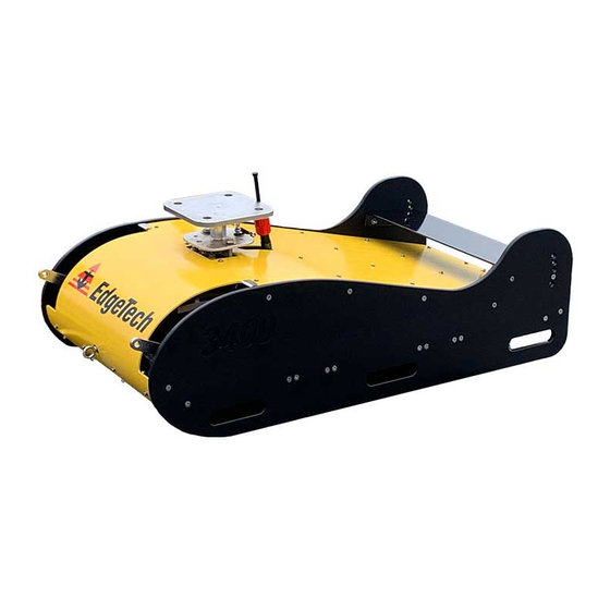
Figure 1-10: Tow Cable 1.3.3 3400 Standard Towfish The standard 3400 is a hydrodynamic towfish designed to carry dual 2-16 kHz transducers and a large segmented PVDF array for sub-bottom surveys. The vehicle is stable, durable, and portable enough to be easily maneuvered on deck and in the water. -
Page 31: 3400 Tow Vehicle Pole Mounting Kit
1.3.4 3400 Tow Vehicle Pole Mounting Kit The 3400 Pole Mounting Kit is necessary to mount the towfish using an EdgeTech designed mount attachment plate to a user-supplied pole. The 3400 Pole Mounting kit is delivered with a pole mount... -
Page 32: 3400 Options
1.3.5.1 3400 OTS (Over-The-Side) Vehicle Option The 3400 Over-The-Side Mount configuration option provides the body form and hardware for pole mounting the vehicle over a vessel's side and provides for different transducer configurations. Figure 1-15: Side View of 3400 OTS Vehicle Configuration Option... -
Page 33: Amplifier Option
Figure 1-16: Forward View of 3400 OTS Vehicle Configuration Option 1.3.5.2 Amplifier Option The 3400 Amplifier option integrates an amplifier into the 3400 system providing increased power to the towfish transducers depending on the amplifier model purchased. Increased power improves penetration and deeper water performance. -
Page 34: Specifications
2-14 2.0 SPECIFICATIONS The 3400 Sub-Bottom Profiling System specifications include electrical, mechanical, and environmental characteristics for the Portable Topside Processor, Laptop, 3400 Tow Vehicle, and the 50 Meter Tow Cable. 2.1 3400 Vehicle Specifications 2.1.1 3400 Sonar Specifications 2.1.1.1 3400 Towfish Standard 2-16 kHz Sonar Specifications... -
Page 35: 3400 Ots Specifications
100m (329 ft) 4 Mbits/sec (typical), Digital Link 2 channels of sub-bottom data plus sensor data Input Voltage: 120/240 VAC input Table 2-3: 3400 Standard Towfish Specifications 2.1.2.2 3400 OTS Specifications SPECIFICATION VALUES Size (Length x Width x Height): 116.84 cm x 74.88 cm x 50.55 cm (46 in x 29.48 in x 17.9 in) Weight in air: 145 kg (320 lb.) -
Page 36: 3400 Topside Electrical Specifications
(32 lb.) Operating Temp. 0–45°C (32–113° F) Storage Temp. -30–70°C (-22–158° F) Operating relative humidity 0-95% (non-condensing) Table 2-5: 3400 Topside General Specifications 2.2.1.2 3400 Topside Electrical Specifications SPECIFICATION TYPE VALUE Input Voltage 120/240 VAC, 50/60 Hz, auto-switching Input Power... -
Page 37: Amplifier Option Physical Specifications
Power to Vehicle To Be Determined Amplifier Interface cable 0022676 3400 OTS I/O Ports Interface Cable between 3400 Sea Cable Port and the 3400 Amplifier Interface Panel. Table 2-9: Amplifier Option Electrical Specifications 2.2.2 3400 Kevlar Tow Cable Specifications The 3400 Tow Cable Specifications are shown below:... -
Page 38: Table 2-10: 50-Meter Tow Cable Specification
(2) # 14 AWG Voltage Rating 300 volts Table 2-10: 50-Meter Tow Cable Specification NOTE: Cables do not come standard with the system and must be specified upon purchase. For more information about cable options, contact USTOMER ERVICE 3400 Portable Sub-bottom System 0021270_REV_C... -
Page 39: Mechanical Drawings
2-19 2.2.3 Mechanical Drawings 2.2.3.1 3400 Standard Towfish ICD Figure 2-1: 3400 Towfish ICD (Click Image To Open Attached PDF) -
Page 40: 3400 Standard Towfish With Pole Mounting Hardware
2-20 2.2.3.2 3400 Standard Towfish with Pole Mounting Hardware Figure 2-2: 3400 Towfish With Pole Mounting Hardware ICD (Click Image To Open Attached PDF) 3400 Portable Sub-bottom System 0021270_REV_D... -
Page 41: 3400 Ots Vehicle Icd
2-21 2.2.3.3 3400 OTS Vehicle ICD Figure 2-3: 3400 OTS Vehicle ICD (Click Image to Open Attached PDF) -
Page 42: 3400 Topside Icd
2-22 2.2.3.4 3400 Topside ICD Figure 2-4: 3400 Topside ICD (Click Image To Open Attached PDF) 3400 Portable Sub-bottom System 0021270_REV_D... -
Page 43: 3400 Topside Case Icd
2-23 2.2.3.5 3400 Topside Case ICD Figure 2-5 3400 Topside Case ICD (Click Image To Open Attached PDF) -
Page 44: 3400 Pole Mount Plate Icd
2-24 2.2.3.6 3400 Pole Mount Plate ICD Figure 2-6: 3400 SBP Pole Mounting Plate ICD 3400 Portable Sub-bottom System 0021270_REV_D... -
Page 45: 3400 Ots Mounting Flange Icd
2-25 2.2.3.7 3400 OTS Mounting Flange ICD Figure 2-7: 3400 OTS Vehicle Mounting Flange... -
Page 46: 3400 Technical Descriptions
PVDF sub-bottom receiver, and an internal sonar processor. The towfish receives power and data from a tow cable connected to the 3400 Topside on a survey vessel. Sonar signal is generated by the transducers, received by the PVDF receiver, amplified, digitized, and combined with towfish sensor data before being sent to the 3400 Topside Processor. -
Page 47: 3400 Standard System Connection Diagram
3-27 3.1.1 3400 Standard System Connection Diagram Figure 3-2: 3400 System Connection Diagram... -
Page 48: 3400 Standard Towfish Electronics Bottle And End Cap Diagrams
3-28 3.1.2 3400 Standard Towfish Electronics Bottle and End Cap Diagrams Figure 3-3: 3400 Electronics Bottle ICD 3400 Portable Sub-bottom System 0021270_REV_D... -
Page 49: Figure 3-4: Sonar Processor Endcap Diagram
3-29 Figure 3-4: Sonar Processor Endcap Diagram... -
Page 50: Figure 3-5: 3400 Electronics Bottle Pinouts
3-30 Figure 3-5: 3400 Electronics Bottle Pinouts 3400 Portable Sub-bottom System 0021270_REV_D... -
Page 51: 3400 Standard Towfish Cable And Connector Diagrams
3-31 3.1.3 3400 Standard Towfish Cable and Connector Diagrams Figure 3-6: Sub Cable T Splice 3400 SBP Tow Cable to Bottle, Transformer, and Tow Cable... -
Page 52: Figure 3-7: 3400 Sbp 50 Meter Tow Cable
3-32 Figure 3-7: 3400 SBP 50 Meter Tow Cable Page 1 3400 Portable Sub-bottom System 0021270_REV_D... -
Page 53: Figure 3-8: 3400 Sbp 50 Meter Tow Cable
3-33 Figure 3-8: 3400 SBP 50 Meter Tow Cable Page 2... -
Page 54: Figure 3-9: Tow Cable To Tow Fish Pinouts (Wet End)
3-34 Figure 3-9: Tow Cable to Tow Fish Pinouts (Wet End) 3400 Portable Sub-bottom System 0021270_REV_D... -
Page 55: 3400 Portable Topside Technical Description
3.2 3400 Portable Topside Technical Description The 3400 portable topside provides power to the towfish while acting as a digital link between the towfish and a topside computer with the Discover application installed on it to process and record sonar data. The digital link also provides input connections for supporting survey, navigation devices, and triggers. -
Page 56: 3400 Amplifier Option Technical Description
Figure 3-11: 3400 Topside Rear Panel 3.3 3400 Amplifier Option Technical Description The 3400 Amplifier option integrates an amplifier into the 3400 system providing increased power to the vehicle transducers depending on the amplifier model purchased. Increased power improves penetration and deeper water performance. -
Page 57: Figure 3-13: Back Panel Amplifier And Connector Panel
Table 3-3: Amplifier Front Panel Controls and Indicator Lights Figure 3-13: Back Panel Amplifier and Connector Panel BACK CONNECTOR PANEL A pin-out MS3102A-20-27P connector connects the amplifier to the 3400 J1 3400 I\O Connector topside Sea Cable port using the amplifier interface cable. -
Page 58: Amplifier Rack Mount
3-38 3.3.1 Amplifier Rack Mount Figure 3-14: Amplifier Rack Mount ICD (Click Image To Open Attached PDF) -
Page 59: Figure 3-15: Amplifier Back Panel Interface To 3400
3-39 Figure 3-15: Amplifier Back Panel Interface to 3400... -
Page 60: Amplifier Connection Diagram
3-40 3.3.2 Amplifier Connection Diagram Figure 3-16: Amplifier Connection Diagram (3400 OTS Vehicle Variant Depicted- Connections Are The Same Regardless of Variant) -
Page 61: Amplifier Cable Diagram
3-41 3.3.3 Amplifier Cable Diagram Figure 3-17: Amplifier to 3400 Topside Interface Cable... -
Page 62: 3400 Ots (Over-The-Side) Technical Description
The vehicle receives power and data from a tow cable connected to the 3400 Topside on a survey vessel. Sonar signal is generated by the transducers, received by the PVDF receiver, amplified, digitized, and combined with vehicle sensor data before being sent to the 3400 topside processor. -
Page 63: 3400 Ots Option Connection Diagram
3-43 3.4.1 3400 OTS Option Connection Diagram Figure 3-19: 3400 OTS Option Connection Diagram... -
Page 64: 3400 Ots Electronics Bottle
3-44 3.4.2 3400 OTS Electronics Bottle Figure 3-20: 3400 OTS Electronics Bottle (Same as standard 3400) -
Page 65: Figure 3-21: 3400 Ots Electronics Bottle Endcap
3-45 Figure 3-21: 3400 OTS Electronics Bottle Endcap... -
Page 66: Figure 3-22: 3400 Ots Pinouts
3-46 Figure 3-22: 3400 OTS Pinouts... -
Page 67: 3400 Ots Vehicle Cable And Connector Diagrams
3-47 3.4.3 3400 OTS Vehicle Cable and Connector Diagrams Figure 3-23: Sub Cable T Splice 3400 OTS Tow Cable to Bottle, Transformer, and Tow Cable... -
Page 68: Figure 3-24: 3400 Ots 50 Meter Tow Cable
3-48 Figure 3-24: 3400 OTS 50 Meter Tow Cable Page 1... -
Page 69: Figure 3-25: 3400 Ots 50 Meter Tow Cable
3-49 Figure 3-25: 3400 OTS 50 Meter Tow Cable Page 2... -
Page 70: Figure 3-26: Tow Cable To Tow Fish Pinouts (Wet End)
3-50 Figure 3-26: Tow Cable to Tow Fish Pinouts (Wet End) -
Page 71: Setup And Activation
Review the packing list and verify all the listed items are included. Again, if any damage is found, report it to the carrier and EdgeTech. If any items are missing, immediately contact EdgeTech. Do not install or operate any equipment that appears to be damaged. -
Page 72: Power Requirements
Navigation System. The devices are connected to the system by plugging them into the COM A or COM B serial ports located on the rear panel of the 3400 Topside. Optionally they could be connected to the serial port of the computer as well. Configuration instructions are found in the... -
Page 73: 3400 Portable Topside Placement
Tow Vehicle. 4.1.5 Connecting the System Components WARNING! NEVER attempt to tow or lift the 3400 Tow Vehicle with the eye bolts at the nose or tail. These are to be used for auxiliary safety lines. WARNING! Do not connect the tow cable to the 3400 Portable Topside before connecting it to the tow vehicle;... -
Page 74: Connecting And Attaching The Tow Cable To The Tow Vehicle
4.1.7 3400 Portable Topside Connection and Activation 3400 S The following procedure describes how to connect the 3400 Portable Topside system. A YSTEM is provided in the section of this manual to assist. -
Page 75: Connecting 3400 System Components
1. Check to make sure the power entry module is in the Off position and the front panel switch is in the off position before connecting the supplied AC Power Cable (switch position = DOWN). 2. Connect the 3400 Topside to a source of AC power using the AC power cable. (Check system power specifications). -
Page 76: Connecting 3400 Systems Components And Optional Amplifier
1. Check to make sure the power entry module is in the Off position and the front panel switch is in the off position before connecting the supplied AC Power Cable (switch position = DOWN). 2. Connect the 3400 Topside to a source of AC power using the AC power cable. (Check system power specifications). -
Page 77: Activating The System
The Ethernet LAN connection is made using an ethernet cable. The cable uses a standard RJ-45 Ethernet plug for direct connection to the RJ-45 LAN jack on a Laptop. The 3400 Topside auto-senses straight and crossover Ethernet cables. The following steps should be taken on the Laptop to use the Ethernet LAN connection: 1. -
Page 78: Performing Sub Bottom Pre-Deployment Checks
A red Power Indicator LED. When illuminated, AC power is applied to the Power Button Light topside. A green Link indicator LED. Flashes, while the 3400 Topside is establishing a reliable communications link with the side-scan sonar. Illuminates Link Indicator Light continuously when a reliable communications link with the sonar is established. -
Page 79: Figure 4-5: Discover 3400 Application Window
4-59 back and navigation is present. The Discover 3400 Application Windows is shown in the figure below, and the results of a tap test are displayed in 4-9. IGURE NOTE: See the 3400 S for detailed software ISCOVER OFTWARE ANUAL information. -
Page 80: Figure 4-7: Towfish Control Tab-Pulse And Transmit Level Called Out
Sub-Bottom Waterfall Display in Discover. Streaks or noise spikes should be visible in the Sub- 4-9. This verifies the receive channel is operating. Bottom Display, as shown in IGURE Figure 4-9: Tap Test Results 3400 Portable Sub-bottom System 0021270_REV_C... -
Page 81: 3400 Tow Vehicle Deployment
4.1.9 3400 Tow Vehicle Deployment The 3400 Tow Vehicle can be towed using the tow cable purchased with the vehicle. The towfish end of the cable should be secured to the bridle shackle with the cable grip, and the tow cable is then run down along a towfish bridle arm to the connector where both ends are mated. -
Page 82: Figure 4-11: Towfish Deployment
3.5 knots. This factory setting is position 4, or the fourth position down out of five for the elevator's trailing edge. Adjust the tow point to position 5 or the lowest trailing edge position for higher tow speeds. 3400 Portable Sub-bottom System 0021270_REV_C... -
Page 83: Obtaining The Best Sonar Imagery When Towing
10 kHz is 20 degrees. For example, if you are transmitting a 2 to 15 kHz FM pulse using a Tow Vehicle with a 0.5-meter long receiving array, such as in the 3400 Tow Vehicle, you must keep the Tow Vehicle from pitching more than about 7 degrees in either direction, or 2 ����... -
Page 84: Ahrs Usage
• been updated to reflect the changes. • The standard 3400 towfish currently supports depths no greater than 100 meters. • The results listed in these tables are calculated using the Woods Hole WHOI cable program with best-estimated parameters for vehicle weight, drag, lift, and buoyancy, as well as cable weight and stiffness. -
Page 85: Table 4-3: 3400 25-Meter With Lead Pack Installed Layback Chart
4-65 TOWED 3400 WITH LEAD WEIGHT PACK INSTALLED AND 25 METERS OF CABLE (PN# 0020874) PAID OUT Down Angle Speed Speed Cable Paid Out Max Cable Depth Distance Behind from Horiz. (kts) (m/s) Tension (N) Ship (m) (deg) 2.00 1.03 2.50... -
Page 86: U-Hinge Tow Bridle
4-66 TOWED 3400 WITH LEAD WEIGHT PACK INSTALLED AND 50 METERS OF CABLE (PN# 0020874) PAID OUT Down Angle Speed Speed Cable Paid Out Max Cable Depth Distance Behind from Horiz. (kts) (m/s) Tension (N) Ship (m) (deg) 2.00 1.03 2.50... -
Page 87: U-Hinge Tow Bridle Removal Instructions
4-67 Figure 4-13: Bridle Stowed Against Vehicle Figure 4-12: Loosening Bridle Elbow 4.1.10.2 U-Hinge Tow Bridle Removal Instructions: The U-Hinge Tow Bridle can be removed either at the flanges at the bridle's base or higher up the bridle at the elbows. Removing the bridle at the flanges at the base of the bridle. -
Page 88: Figure 4-14: Nut And Bolt Location Looking Through Handhold Hole
4-68 [2] Split Rings Figure 4-14: Nut and Bolt Location Looking Through Handhold Hole. 3400 Portable Sub-bottom System 0021270_REV_C... -
Page 89: Figure 4-15: Bridle Arm Bolt Locations- 2 Bolts Port And Starboard Sides
4-69 [2] 3/8”-16 Socket Head Bolts with 5/16” Drive Size Figure 4-15: Bridle Arm Bolt Locations- 2 Bolts Port and Starboard Sides... -
Page 90: Figure 4-16: Bridle Removal Tool Orientation
3. Lift the bridle from towfish and store. Removing bridle from the bridle elbows. REQUIRED TOOLS 3/4” Wrench • • Adjustable Crescent Wrench Plyers • 3400 Portable Sub-bottom System 0021270_REV_C... -
Page 91: Figure 4-17: Bridle Removal: Split Ring Removal
4-71 Instructions: 1. Remove split rings from left and right 1/2-inch bolts at Bridle Elbows with plyers. Figure 4-17: Bridle Removal: Split Ring Removal 2. Remove left and right 1/2 inch bolt, 1/2 inch nut, and washers using 3/4” wrenches or adjustable crescent wrenches. -
Page 92: Pole Mounting The 3400 Tow Vehicle
If you purchased this option with the standard 3400 Towfish, the Pole Mount Flange comes preinstalled. If you buy the pole mounting kit later or have previously configured the 3400 towfish for towing, you will need to remove the tow bridle, remove the weights in the forward section of the vehicle, remove the rear elevator, and install the pole mounting flange. -
Page 93: Figure 4-20: 3400 Pole Mount Instruction-Front Panel Removal With (12) Screws And Eye Bolt Called Out
Screwdriver and unthreading the front eyebolt using a 7/16” wrench. Figure 4-20: 3400 Pole Mount Instruction-Front Panel Removal With (12) Screws and Eye Bolt Called Out 2. Loosen and remove (4) hex nuts and (4) washers using the 7/16” Combination Wrench or Adjustable Crescent Wrench. -
Page 94: Removing The Rear Elevator
4-74 Figure 4-22: 3400 Pole Mount Instruction- Weight Removal-Location of Bolt Heads on Bottom of Vehicle 3. Lift the weight block(s) from bolts and remove them from the vehicle. Instructions for Reinstalling or Adding Weights 1. Install additional or a replacement weight block by aligning the weights four bolt holes with the towfish’s four bolts and setting the weights into position. -
Page 95: Pole Mount Installation Instructions
4-75 Elevator Hex Screw Positions Figure 4-23: 3400 Pole Mount Instruction-Elevator Hex Screw Positions Instructions: 1. Remove the [4] 1/4”-20 Flat Head Hex-head screws with a 5/32” Allen wrench on both side panels and a 7/16” wrench. 2. Remove and save the [4] Shoulder washers from the elevator. - Page 96 2. Remove the [6] 1/2”-13 set screws in the vehicle's sidewalls using a 1/4" Allen key or T-handle. The set screws may be secured with 2047 Loctite, in which case a significant amount of hand torque may be required. 3400 Portable Sub-bottom System 0021270_REV_C...
-
Page 97: Figure 4-24: Port And Starboard Set Screw Removal
4-77 Set Screw Removal Figure 4-24: Port and Starboard Set Screw Removal 3. Take the pole mount assembly and place it on the top of the vehicle, careful to let the cable connector's locking sleeve pass through the appropriate hole. Second Forward Dorsal Cable Hole Figure 4-25: Forward Dorsal Pole Mount Cable Hole Position... -
Page 98: Figure 4-26: Forward Dorsal Bolt Locking Washer And Molybdenum Disulfide Coating
Molybdenum Disulfide on Bolt Figure 4-26: Forward Dorsal Bolt Locking Washer and Molybdenum Disulfide Coating Forward Dorsal Bolt Position. Threaded in a few turns but not tightened Figure 4-27: Forward Dorsal Pole Mount Bolt Position 3400 Portable Sub-bottom System 0021270_REV_C... -
Page 99: Figure 4-28: Port And Starboard Pole Mount Bolt Positions
4-79 5. Apply a generous amount of Molybdenum Disulfide to the threads of the [6] 1/2”-13 2.0” length (~51 mm length) bolts if they are not already lubricated from previous steps. Insert one of the 6 1/2” ID (~13 mm ID) wedge lock washer pairs onto each bolt. Thread them into the sidewall tee- nuts. -
Page 100: Figure 4-30: 3400 Sideview With Pole Mount Installed
7. Insert the [4] 3/4” Bolts down through the [4] 4/4 flat washers, the holes of your pole flange, the upper plate flange holes of EdgeTech’s mount, the [4] flat washers, the [4] lock washers, and [4] a 3/4” Hex nuts. Thread and tighten using a 3/4” wrench and the adjustable wrench to assist. -
Page 101: Figure 4-31: Towfish Mounting Flange To Pole Mount Flange Bolt Assembly
4-81 Hex Bolt Flat Washer Hex Nut Locking Washer Clevis Pin Figure 4-31: Towfish Mounting Flange to Pole Mount Flange Bolt Assembly... -
Page 102: Utilizing The Forward And Aft Eye Bolts
4.1.16 Utilizing the Forward and Aft Eye Bolts The 3400 Towfish includes two auxiliary eye bolts located on the vehicle's central bow and central stern portions. These provide additional stabilization when attached to the towing vessel with tensioned safety lines. -
Page 103: 3400 Ots Setup And Activation
Figure 4-34: Aft Eye Bolt 4.2 3400 OTS Setup and Activation 4.2.1 3400 OTS Unpacking and Inspection The 3400 OTS Vehicle, Portable Topside, and Tow Cable are shipped in separate, reusable, heavy-duty transport cases. Essential cables and documentation are also included. -
Page 104: Installing Rubber U-Shaped Safety Trim
Review the packing list and verify all the listed items are included. Again, if any damage is found, report it to the carrier and EdgeTech. If any items are missing, immediately contact EdgeTech. Do not install or operate any equipment that appears to be damaged. -
Page 105: Power Requirements
Figure 4-35: 3400 OTS Rubber Trim Installation 4.2.3 Power Requirements The 3400 power requirements are 120–220 VAC and 50/60 Hz, and the input voltage is auto-sensing. 4.2.3.1 Use of an Uninterruptable Power Supply The power source should be continuously free of high amplitude, high-frequency transients, as this type of interference could cause degraded performance or damage to the equipment. -
Page 106: Changing To A Non-Us Power Plug
Navigation System. The devices are connected to the system by plugging them into the COM A or COM B serial ports located on the rear panel of the 3400 Topside. Optionally they could be connected to the serial port of the computer as well. Configuration instructions are found in the... -
Page 107: Connecting The 3400 Ots System Components
The location should also enable direct communications with the deck crew that is handling the tow vehicle. 4.2.6 Connecting the 3400 OTS System Components 4.2.6.1 Instructions on Running Tow Cable to Connector Users must run the tow cable through the OTS Mount and cable clip and mate it to the vehicle’s tow cable... -
Page 108: Figure 4-38: Ots Mounting Flange
3. Mate the two cable connectors and secure the cable to the vehicle by installing the cable clip over the tow cable and securing it to the vehicle but threading the [2] 1/4”-20 pan head bolts using the 5/32” Allen wrench. 3400 Portable Sub-bottom System 0021270_REV_C... -
Page 109: Instructions On Securing Ots Mount To Vessels Mounting Hardware
Figure 4-41: OTS Flange Bolt Assembly Figure 4-40: OTS Mounting Flange with Bolts Installed 4.2.7 3400 OTS Portable Topside Connection and Activation The 3400 OTS uses the same portable topside as the standard 3400 system. Connection and system activation is explained in the 3400 P... -
Page 110: Performing Sub-Bottom Pre-Deployment Checks
OTTOM EPLOYMENT HECKS 4.2.9 3400 OTS Vehicle Deployment The 3400 OTS is designed to be securely mounted to a customer’s pole mounting over a vessel's side. It is not designed to be towed. 4.2.9.1 Obtaining the Best Sonar Imagery To generate good sonar imagery, the vehicle's pitch, which is how much in degrees the nose is angled up or down, must be less than one-half of the -6-dB beamwidth of the acoustic pulse its highest frequency—... -
Page 111: Ahrs Usage
Rough sea conditions tend to move the car up and down vertically, causing oscillations in the images. Discover Sub-Bottom has a swell filter that will help reduce 3400 S the heave effect on the record. Refer to the for details. -
Page 112: Maintenance
5.2 Cleaning the Tow Vehicle and Tow Cable After Use After retrieving the 3400 Towfish from the water, use a hose to wash it down, along with the tow cable, with clean, fresh water. Thoroughly spray the transducers and the hydrophone arrays from underneath the tow vehicle and remove any buildup of debris that may have been trapped inside. -
Page 113: Inspecting And Cleaning The Underwater Connectors
5.5 Altering the 3400 Towfish Configuration The procedures below describe how to alter the configuration of the 3400 Tow Vehicle. There is little to no reason to disassemble the tow vehicle. Should you need to disassemble the tow vehicle for any reason, contact before any attempts to disassemble the vehicle. -
Page 114: Adjusting Or Removing The Rear Elevator
Adding or Removing the Rear Elevator: 1. Remove the [4] 1/4”-20 Flat Head Hex-head screws with a 5/32 Allen wrench on both side panels and a 7/16” wrench. 2. Remove and save the [4] Shoulder washers from the elevator. 3400 Portable Sub-bottom System 0021270_REV_C... -
Page 115: Removing The Sonar Processor Bottle
5-95 Reverse this procedure to mount the elevator to the vehicle. To change the position of the elevators: 1. Remove the [2] 1/4”-20 Flat Head Hex-head screws with a 5/32 Allen wrench on both side panels and a 7/16” wrench. 2. -
Page 116: Figure 5-3: Electronics Bottle Cotter Pin Removal
5-96 Cotter Pins Figure 5-3: Electronics Bottle Cotter Pin Removal 4. Pull back the center clip and lift each latch. Disconnect the clip from the strike 3400 Portable Sub-bottom System 0021270_REV_C... -
Page 117: Figure 5-4: Electronic Bottle Latch And Rubber Strip Locations
5-97 (2) Latches (2) Rubber Strips Figure 5-4: Electronic Bottle Latch and Rubber Strip Locations 5. Rubber strips protect the bottle from the latches. Be sure these rubber strips stay inside the vehicle while the bottle is removed. When reinstalling the bottle, replace the rubber between the latch straps and the bottle. -
Page 118: Troubleshooting
6-98 6.0 TROUBLESHOOTING The 3400 Towfish is a complex computer-controlled system that requires engineering expertise and the proper test equipment to service. For any service or troubleshooting, please contact CUSTOMER SERVICE for updated instructions, drawings, documentation, tools, and guidance. This ensures success and is necessary to maintain the product’s warranty. - Page 119 6-99 2. Insert USB3 flash drive in a blue USB3 port. 3. Start topside and be prepared to press F⋆⋆ key when prompted: a. If the topside is rack mount, press F11. b. If the topside is a laptop, press F12. 4.
-
Page 120: Ahrs Calibration
6-100 6.2 AHRS Calibration The Attitude Heading Reference System (AHRS) is calibrated at the EdgeTech manufacturing facility and should not require additional calibration. Should the AHRS in the vehicle lose its calibration, please contact CUSTOMER SERVICE for assistance. -
Page 121: Kits
Table 7-2: 3400 Topside Spares Kit 0021539 ASSY SUB KIT 3400 SBP POLE MOUNT KIT Part Description 0021310 ASSY SUB POLE MOUNT 3400 REMOVABLE 0021547 ASSY TOP CABLE 3400 POE SBP KEVLAR 0.587 DECK CABLE 10M Table 7-3: 3400 SBP Pole Mount Kit... -
Page 122: Figure 7-1: 3400 Ots Vehicle Spares Kit
TOOL WRENCH RATCHET 3400 3/8 INCH DRIVE 8.00 INCH LENGTH QUICK 0022164 RELEASE 0022005 ASSY TOP SPARES 0023645 TOOL T-HANDLE ALLEN KEY 3400 1/4 INCH SIZE 6.0 INCH LENGTH Table 7-4: 3400 Pole-Mounting Kit 0021642 ASSY TOP SPARES 3400 TOW FISH OTS...
Need help?
Do you have a question about the 3400 and is the answer not in the manual?
Questions and answers