
Subscribe to Our Youtube Channel
Related Manuals for Edgetech 701 DIGITAL LINK


Summary of Contents for Edgetech 701 DIGITAL LINK
- Page 1 701 DIGITAL LINK U S E R H A R D W A R E M A N U A L 0004809_REV_ F 4/28/2020 EdgeTech 4 Little Brook Road West Wareham, MA 02576 Tel: (508) 291-0057 Fax: (508) 291-2491 www.EdgeTech.com...
- Page 2 The information, figures, and specifications in this manual are proprietary. They are issued in strict confidence on condition that they not be copied, reprinted, or disclosed to a Third-Party, either wholly or in part, without the prior written consent of EdgeTech. Any reproduction of EdgeTech supplied software or file sharing is strictly prohibited.
-
Page 3: Attention - Read This First
ATTENTION – READ THIS FIRST! All personnel involved with the installation, operation, or maintenance of the equipment described in this manual should read and understand the warnings and cautions provided below. CAUTION! This equipment contains devices that are extremely sensitive to static electricity. -
Page 4: Hardware Variations And Compatibility
HARDWARE VARIATIONS AND COMPATIBILITY The 701 Digital Link contains both standard and proprietary hardware. At times, EdgeTech may change the standard components due to their availability or performance improvements. Although the component manufacturers—along with their models and styles—may change from unit to unit, replacement parts will generally be interchangeable. -
Page 5: About This Document
ABOUT THIS DOCUMENT We, the employees at EdgeTech, would like to thank you for purchasing a 701 Digital Link. At EdgeTech, it is our policy to provide high-quality, cost-effective products and support services that meet or exceed your requirements. We also strive to deliver them on-time and to continuously look for ways to improve them. -
Page 6: Warranty Statement
All equipment manufactured by EdgeTech is warranted against defective components and workmanship for a period of one year after shipment. Warranty repair will be done by EdgeTech free of charge. Shipping costs are to be borne by the customer. Malfunction due to improper use is not covered in the warranty, and EdgeTech disclaims any liability for consequential damage resulting from defects in the performance of the equipment. -
Page 7: Software Service Overview
Software Updates and Enhancements EdgeTech customers can download new software releases with all modifications and enhancements from the EdgeTech FTP site. Major software issues, should they occur, will be reported directly to the customer. New software releases consist of the following: Software enhancements that are not on the price list •... -
Page 8: Returned Material Authorization
Refer to the RMA number on all documentation and correspondences. All returned materials must be shipped prepaid. Freight collect shipments will not be accepted. All equipment should be adequately insured for shipping, but equipment belonging to EdgeTech must be insured for full value. -
Page 9: Customer Service
CUSTOMER SERVICE Customer service personnel at EdgeTech are always eager to hear from users of our products. Your feedback is welcome and is a valuable source of information which we use to continually improve these products. Therefore, we encourage you to contact EdgeTech Customer Service to offer any suggestions... -
Page 10: Company Background
— for the acquisition of underwater data, including marine, estuarine, and coastal applications — for over 50 years. EdgeTech responds to the needs of the Scientific, Naval, and Offshore communities by providing industry- leading equipment — such as Sub-Bottom Profilers, Side Scan Sonar, Acoustic Releases, USBL Positioning Systems, and Bathymetric Systems —... -
Page 11: Table Of Contents
TABLE OF CONTENTS ATTENTION – READ THIS FIRST! ......................iii Warnings, Cautions, and Notes ........................ iii HARDWARE VARIATIONS AND COMPATIBILITY .................. iv ABOUT THIS DOCUMENT ........................v Purpose of this Manual ..........................v Liability ..............................v Revision History ............................v WARRANTY STATEMENT ........................ - Page 12 MAINTENANCE ........................4-1 TROUBLESHOOTING .......................5-1 701-DL Digital Link Troubleshooting Guide ................5-1 701-DL with 2U Computer Troubleshooting Guide ..............5-2 Part Numbers for Major Components ..................5-2 COMPUTER SYSTEM RESTORE ....................A-1 PRINTERS ..........................B-1 701 Digital Link 0004809_REV_F...
-
Page 13: List Of Figures
xiii LIST OF FIGURES Figure 3-1: 701-DL Front and Back Panels ....................3-5 Figure 3-2: 701 With Computer Front Panel ....................3-7 Figure 3-3: 701 DL With Computer Rear Panel ..................3-8... - Page 14 Table 3-1: 701-DL Controls, Indicators, and Connections ................3-4 Table 3-2: 701 DL With Computer Controls, Indicators and Connections ..........3-6 Table 5-1: 701-DL Digital Link Troubleshooting Guide................5-1 Table 5-2: 701-DL Rackmount Troubleshooting Chart................5-2 701 Digital Link 0004809_REV_F...
-
Page 15: Overview
701-DL, monitors and controls the attached towfish and displays and records acquired sonar and sensor data. The 701-DL fits a 19-inch rack and is delivered mounted independently in a rugged 2U-SKB case or mounted with an EdgeTech provided computer in a rugged 6U case. 1.1 Applications... -
Page 16: Specifications
400 VDC 400 VDC Processor — Intel Core, I7, 3.6 GHz Quad-Core Memory — 4 GB, 1333 MHz — DVD/RW drive Data storage 1-TB hard drive (data) 500-GB hard drive (OS) Display — 23.6-inch LCD monitor 701 Digital Link 0004809_REV_F... -
Page 17: Table 2-1: 701-Dl Specifications
Keyboard — High impact industrial keyboard Pointing device — High impact industrial trackball External trigger (1) Ethernet (1) Ethernet (1) Trigger (3) RS-232 I/O ports (6) USB 2 (2) USB 3 (1) Trigger Table 2-1: 701-DL Specifications... -
Page 18: Setup And Activation
3.0 SETUP AND ACTIVATION EdgeTech designed the 701 Digital Link to be easily set up and activated for operation. Instructions for this process are provided in the subsections to follow. 3.1 Unpacking and Inspection Before unpacking the system components, inspect the shipping containers for any damage. Report any damage to the carrier and EdgeTech. -
Page 19: Connecting The 701-Dl
3.2.1 Connecting the 701-DL All Edgetech Towfish products are supplied with Hardware and Software Manuals that provide specific connection, activation, and testing instructions for each model. General instructions are provided below. WARNING! Never power up the 701-DL with the tow cable disconnected from the tow vehicle. -
Page 20: Connecting To The 701-Dl With Computer
Green indicator. Illuminated when the 701-DL Digital Link is on. BACK PANEL Line VAC Connector Connection for AC power cord. Rocker switch. Switches AC power to POWER switch on the front panel of Line Power Switch the 701-DL Digital Link. AC Fuse AC power fuse. 701 DIGITAL LINK 0004809_REV_F... -
Page 21: Table 3-1: 701-Dl Controls, Indicators, And Connections
FRONT PANEL RJ-45 Standard Ethernet connection for connecting to the external topside Data Connector processor. It provides an input connection for a TTL external trigger that is sent to the Sync Connector towfish. Sea Cable Connector SubConn MCBH4F female connector to sea cable going out to tow vehicle. Table 3-1: 701-DL Controls, Indicators, and Connections... - Page 22 POWER Switch LAN, LINK, FISH POWER and POWER indicators LINE VAC connector, DATA SEA CABLE Sea Cable Connector connector Switch, and AC Fuse connector VAC Connector, Power Sea Cable Switch, Fuse Data Connector Connector Grounding Lug SYNC connector Figure 3-1: 701-DL Front and Back Panels...
-
Page 23: 701-Dl With Computer Controls, Indicators, And Connections
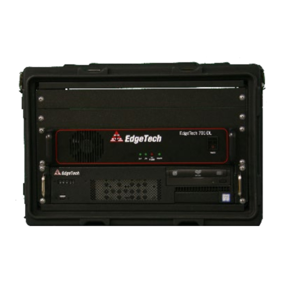
3.2.3 701-DL with Computer Controls, Indicators, and Connections The 4205-Rack Mount (701-DL and 2U-CPU Combo) controls, indicators, and connections are described below: FRONT PANEL 701-DL Power Switch Rocker switch. Turns the 701-DL Link on or off. Green indicator. Flashes continuously when an Ethernet connection is LAN Indicator Light established. - Page 24 POWER switch SYSTEM POWER indicator LINK indicator LAN indicator FISH POWER indicator DVD drive USB connectors Figure 3-2: 701 With Computer Front Panel...
- Page 25 ETHERNET connector SEA CABLE connector VAC INPUT connector SYNC connector POWER switch COM 1-NAV connector ETHERNET connector Video Card VAC INPUT connector POWER switch USB connectors Figure 3-3: 701 DL With Computer Rear Panel...
-
Page 26: Activating The 701-Dl
After recovering a tow vehicle from a survey, power down the topside computer and 701-DL. The unit can then be safely disconnected from the tow vehicle. If the next survey is not for an extended time period, EdgeTech recommends storing the unit in its original shipping container in a safe and dry environment 701 Digital Link... -
Page 27: Maintenance
4.0 MAINTENANCE The 701 Digital Link is ruggedly designed and built, and therefore requires little maintenance. However, to ensure long-lasting, reliable service, some periodic maintenance is recommended. Maintenance of the system should be performed regularly or as often as necessary, depending on use. -
Page 28: Troubleshooting
Refer to the manual for modem settings. turned on. After 1- are incorrect. minute flashing should stop, and the indicator Check topside on different Towfish. 4205 Towfish is faulty. should remain lit. Table 5-1: 701-DL Digital Link Troubleshooting Guide. 701 Digital Link 0004809_REV_F... -
Page 29: 701-Dl With 2U Computer Troubleshooting Guide
5.2 701-DL with 2U Computer Troubleshooting Guide This troubleshooting section is for the 701-DL and Computer Combo. SYMPTOM PROBABLE CAUSE CORRECTIVE ACTION The POWER switch is not Verify that the POWER switch located in rear off CPU is in turned on. the on position. -
Page 30: Computer System Restore
12. Remove the USB3 flash drive and restart the topside. 13. Re-boot and click on the Windows icon and navigate to Control Panel > System. Activate Windows using the supplied key code on the rear of the laptop or 2U rack mount computer. 701 Digital Link 0004809_REV_F... -
Page 31: Printers
Ultra 120 • • Ultra 120-HD Ultra 200 HD • • EPC 1086 EPC 1086 Old • • Geoprinter 975 TDU 850 • NOTE: EdgeTech Topsides support the ETHERNET-only Printers listed above. Consult manufacturer’s operating manual printer requirements and set up.
Need help?
Do you have a question about the 701 DIGITAL LINK and is the answer not in the manual?
Questions and answers