
Subscribe to Our Youtube Channel
Related Manuals for Edgetech 3400


Summary of Contents for Edgetech 3400
- Page 1 3400 SUB-BOTTOM SONAR SYSTEM Q U I C K S T A R T G U I D E 0021825_REV_A 8/23/2022 EdgeTech 4 Little Brook Road West Wareham, MA 02576 Tel: (508) 291-0057 Fax: (508) 291-2491 www.EdgeTech.com...
- Page 2 The information, figures, and specifications in this manual are proprietary. They are issued in strict confidence on the condition that they not be copied, reprinted, or disclosed to a third party, either wholly or in part, without the prior written consent of EdgeTech. Any reproduction of EdgeTech-supplied software or file sharing is strictly prohibited.
-
Page 3: Hardware Variations And Compatibility
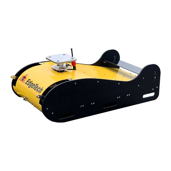
EdgeTech’s proprietary Full Spectrum CHIRP technology to generate high-resolution images of the sub-bottom stratigraphy in oceans, lakes, and rivers and provide excellent penetration of various bottom types. There are currently five 3400 variants with unique configurations designed to meet surveyor needs. - Page 4 Although the component manufacturers and their models and styles may change from unit to unit, replacement parts will generally be interchangeable. EdgeTech will make every effort to see that replacement components are interchangeable and use the same software drivers (if applicable). At times, however, direct replacements may not exist. When this happens, EdgeTech will provide the necessary drivers with the replacement part, if applicable.
-
Page 5: Customer Service
CUSTOMER SERVICE Customer service personnel at EdgeTech are always eager to hear from users of our products. Your feedback is welcome and a valuable source of information that we continually use to improve these products. Therefore, we encourage you to contact EdgeTech Customer Service to offer any suggestions... -
Page 6: Attention - Read This First
Therefore, use caution when the electronics are removed from their containers for servicing. WARNING! Do not connect the tow cable to the 3400 Topside before connecting it to the vehicle; otherwise, injury or death can occur if the tow cable's exposed connector is energized. Always connect the tow cable to the vehicle first. -
Page 7: Revision History
Revision History REVISION DESCRIPTION DATE APPROVAL Release to Production 8/23/2022... -
Page 8: Table Of Contents
Revision History ............................vii TABLE OF CONTENTS ........................viii SYSTEM SETUP ........................1-1 Standard 3400 Hardware Configuration..................1-1 3400 System With Amplifier Configuration ................1-3 SYSTEM ACTIVATION AND TESTING ..................2-6 Activating the System ........................ 2-6 Performing Sub Bottom Pre-Deployment Checks ..............2-7 DEPLOYMENT ........................ -
Page 9: System Setup
• If it is a towed 3400 system, the tow cable should be secured to the bridle shackle with a cable grip, and the tow cable is then run down along a towfish bridle arm to the connector, where both ends are mated. - Page 10 Laptop AC Power Connection Navigation Device Serial Connections Ethernet Cable Connections Tow/Sea Cable 3400 AC Power Connection Connection Figure 1-1: 3400 Topside and Computer Connections Figure 1-2: 3400 Sub-Bottom Profiler Connection Diagram 3400 Sub-Bottom Sonar System 0021825_REV_A...
-
Page 11: 3400 System With Amplifier Configuration
AC Power Cables (switch position = DOWN). 2. Connect the 3400 Topside and amplifier to a source of AC power using the AC power cable. (Check system power specifications). 3. Connect the J2 Connector on the amplifier to the Towfish connector using the supplied tow cable. - Page 12 Always connect the tow cable to the tow vehicle first. If it is a towed 3400, the tow cable should be secured to the bridle shackle with a cable grip, • and the tow cable is then run down along a towfish bridle arm to the connector, where both ends are mated.
- Page 13 Figure 1-4: 3400 OTS Sub-Bottom Profiler and Amplifier Connection Diagram Figure 1-5: 3400 540E Sub-Bottom Profiler and Amplifier Connection Diagram...
-
Page 14: System Activation And Testing
OFTWARE ANUAL 2.1 Activating the System To activate the 3400 Portable Sub-Bottom Profiling System after making all necessary connections: 1. Operate the ON/OFF switch to the ON position (switch position = UP). Observe the front panel LEDs. Figure 2-1: 3400 Topside Front Panel-LED Indicator Lights The Power-on sequence for the LEDs should appear as follows once the power is turned on. -
Page 15: Performing Sub Bottom Pre-Deployment Checks
The Discover Radio Indicator Tabs in the Lower Control Panel on the lower right side of the Discover UI displays the current status and warnings of the 3400 system. Detailed descriptions of status messages are found in the Radio Indicator section of the... - Page 16 Figure 2-4: Discover 3400 Application Window To perform the pre-deployment checks: 1. Follow the instructions in the section of this manual. CTIVATING THE YSTEM 2. Run a Tap Test – Navigate to the Towfish Control Tab, shown in 2-5. IGURE Figure 2-5: The Towfish Control Tab 3.
- Page 17 Figure 2-6: Towfish Control Tab-Pulse and Transmit Level Called Out 4. In the Towfish Control Tab, select a Transmit Pulse using the “Pulse” dropdown. Set “Transmit Level (%)” to “0”. The transducers should begin transmitting (at 0%) and receive data should start scrolling on the Waterfall Display in Discover Sub-Bottom, from right to left.
- Page 18 +90 degrees. Verify that the pitch is working correctly by lifting the vehicle's tail. The pitch value should • read negative and reach a max of -90 degrees. 3400 Sub-Bottom Sonar System 0021825_REV_A...
-
Page 19: Deployment
3-11 3.0 DEPLOYMENT Points to be considered for the deployment of 3400 Vehicles: • Location of the propeller of the vessel. It may be better to deploy from the side of the boat in shallow water. Expected turning direction during deployment. When deploying a towed variant from the side of •... - Page 20 Press to set File Button Directory to be saved to. Figure 3-2: Discover UI-Disk Tab Recording Controls Start recording by clicking the Red Dot Recording button in the shortcut icon bar or Disk Tab Recording Controls. 3400 Sub-Bottom Sonar System 0021825_REV_A...
-
Page 21: Quickstart Guide Checklist
Turn on the laptop and start the Discover software ☐ Power Turn on Topside power ☐ Observe indicator lights on the 3400 topside’s front panels and Discover displays. Watch for the NET indicator in Discover to change from OFF To ON ☐ in Discover Pre-deployment Test Perform pre-deployment rub test ☐...
Need help?
Do you have a question about the 3400 and is the answer not in the manual?
Questions and answers