Table of Contents
Advertisement
Quick Links
Download this manual
See also:
User Manual
Advertisement
Table of Contents
Troubleshooting

Subscribe to Our Youtube Channel
Related Manuals for Edgetech 3100-P


Summary of Contents for Edgetech 3100-P
- Page 1 3100-P PORTABLE SUB-BOTTOM U S E R H A R D W A R E M A N U A L 0004802_REV_F 7/2/2018 EdgeTech 4 Little Brook Road West Wareham, MA 02576 Tel: (508) 291-0057 Fax: (508) 291-2491 www.EdgeTech.com...
- Page 2 The information, figures, and specifications in this manual are proprietary and are issued in strict confidence on condition that they not be copied, reprinted, or disclosed to a third party, either wholly or in part, without the prior, written consent of EdgeTech. Any reproduction of EdgeTech supplied software or file sharing is strictly prohibited.
-
Page 3: Attention - Read This First
ATTENTION – READ THIS FIRST! All personnel involved with the installation, operation, or maintenance of the equipment described in this manual should read and understand the warnings and cautions provided below. CAUTION! This equipment contains devices that are extremely sensitive to static electricity. -
Page 4: Hardware Variations And Compatibility
Although the component manufacturers—along with their models and styles—may change from unit to unit, replacement parts will generally be interchangeable. EdgeTech will make every effort to see that replacement components are interchangeable and use the same software drivers (if applicable). At times, however, direct replacements may not exist. When this happens, EdgeTech will provide the necessary drivers with the replacement part, if applicable. -
Page 5: About This Document
ABOUT THIS DOCUMENT We, the employees at EdgeTech, would like to thank you for purchasing 3100-P. At EdgeTech, it is our policy to provide high-quality, cost-effective products and support services that meet or exceed your requirements. We also strive to deliver them on-time, and to continuously look for ways to improve them. -
Page 6: Warranty Statement
All equipment manufactured by EdgeTech is warranted against defective components and workmanship for a period of one year after shipment. Warranty repair will be done by EdgeTech free of charge. Shipping costs are to be borne by the customer. Malfunction due to improper use is not covered in the warranty, and EdgeTech disclaims any liability for consequential damage resulting from defects in the performance of the equipment. -
Page 7: Software Service Overview
Software Updates and Enhancements EdgeTech customers can download new software releases with all modifications and enhancements from the EdgeTech ftp site. Major software issues, should they occur, will be reported directly to the customer. New software releases consist of the following: •... -
Page 8: Returned Material Authorization
Refer to RMA number on all documentation and correspondences. All returned materials must be shipped prepaid. Freight collect shipments will not be accepted. All equipment should be adequately insured for shipping, but equipment belonging to EdgeTech must be insured for full value. -
Page 9: Customer Service
CUSTOMER SERVICE Customer service personnel at EdgeTech are always eager to hear from users of our products. Your feedback is welcome, and is a valuable source of information which we use to continually improve these products. Therefore, we encourage you to contact EdgeTech Customer Service to offer any suggestions... -
Page 10: Company Background
USBL positioning systems, and bathymetric systems—that have become standards in the industry. EdgeTech has also consistently anticipated and responded to future needs through an active research and development program. Current efforts are focused on the application of cutting-edge CHIRP and acoustic technology. -
Page 11: Table Of Contents
1.1.6 Gaussian Shaped Amplitude Spectrum Outgoing Pulse ............1-3 1.1.7 Reduction of Side Lobes ......................1-3 1.2 Full Spectrum Chirp Technology Applications ................1-3 1.2.1 3100-P Portable Topside ......................1-4 1.2.2 SB-424 and SB-216S Tow Vehicles ..................1-6 1.2.3 35-Meter Kevlar Reinforced Tow Cable ................. 1-7... - Page 12 General Specifications ....................2-1 2.1.1.2 3100-P Power Requirements ..................2-1 2.1.1.3 3100-P Laptop Specifications ..................2-2 2.1.1.4 Interface between 3100-P and Laptop Computer ............2-2 2.1.2 Tiger Board Description ......................2-2 2.1.2.1 Carrier Board ........................2-2 2.1.2.2 Acquisition Board ......................2-3 2.1.2.3...
- Page 13 4.6.1 Disassembling a Tow Vehicle ....................4-4 4.6.2 Reassembling a Tow Vehicle ....................4-6 SECTION 5: TROUBLESHOOTING ....................5-1 5.1 3100-P Portable Topside Troubleshooting ................... 5-2 5.2 Wiring and Connector Pin out Drawings ..................5-3 APPENDIX A: SYSTEM RESTORE ....................A-10...
-
Page 14: List Of Figures
LIST OF FIGURES Figure 1-1: 3100-P Portable Topside Open with Laptop ................1-5 Figure 1-2: 3100-P Portable Topside Internal Components ..............1-5 Figure 1-3: SB-424 and SB-216S Tow Vehicles ................... 1-6 Figure 1-4: 35-Meter Kevlar Reinforced Tow Cable ................... 1-7 Figure 2-1: Tiger Board Set: Carrier (Front view) –... - Page 15 Figure 5-5: Wiring Diagram, Spider Box, SB-216S Tow Vehicle ..............5-8 Figure 5-6: Wiring Diagram, SB-216S Tow Vehicle ..................5-9...
-
Page 16: List Of Tables
LIST OF TABLES Table 2-1: General Specs for 3100-P Portable Topside ................2-1 Table 2-2: Power Requirements ........................ 2-1 Table 2-3: Laptop Specifications ........................ 2-2 Table 2-4: 3100-P / Notebook Computer Interface ................... 2-2 Table 2-5: Tow Vehicle Specifications ......................2-6 Table 2-6: 35-Meter Kevlar Reinforced Tow Cable Specifications ............ -
Page 17: Section 1: Overview
(FM) sub-bottom profiler that uses EdgeTech’s proprietary Full Spectrum chirp technology to generate cross-sectional images of the seabed and collect digital normal incidence reflection data over many frequency ranges. The 3100-P transmits an FM pulse (also called a "chirp pulse") that is linearly swept over a full spectrum frequency range. -
Page 18: High Repeatability
EdgeTech technical support can provide assistance in selecting the best tow vehicle for your application. -
Page 19: Gaussian Shaped Amplitude Spectrum Outgoing Pulse
The effective spatial beam width obtained after processing a full spectrum 2–10 kHz signal, for example is 20 degrees measured at the -3db points. 1.2 Full Spectrum Chirp Technology Applications Applications of the Full Spectrum Chirp Technology used in the 3100-P Sub-Bottom Profiling System include: •... -
Page 20: 3100-P Portable Topside
• Environmental site investigations 1.2.1 3100-P Portable Topside The 3100-P Portable Topside has its electronics housed in a heavy-duty case that is watertight when closed. The case also holds a provided laptop computer that runs the DISCOVER acquisition software CAUTION! Never attempt to ship portable topside units in their Storm Case alone. -
Page 21: Figure 1-1: 3100-P Portable Topside Open With Laptop
Laptop Water-Resistant (when closed) Case Figure 1-1: 3100-P Portable Topside Open with Laptop Main Power Board Power Supply (under aluminum plate) Tiger Board Figure 1-2: 3100-P Portable Topside Internal Components... -
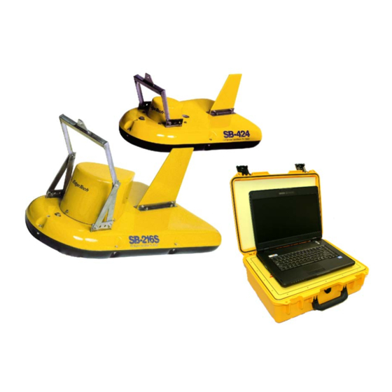
Page 22: Figure 1-3: Sb-424 And Sb-216S Tow Vehicles
A hinged U-framed tow bridle is used for towing, and the tow point location can be adjusted to accommodate different towing speeds and depths. The tow vehicles are each shipped in a wooden crate. SB-424 Tow Vehicle SB-216S Tow Vehicle Figure 1-3: SB-424 and SB-216S Tow Vehicles 3100-P PORTABLE SUB-BOTTOM 0004802_REV_F... -
Page 23: 35-Meter Kevlar Reinforced Tow Cable
1.2.3 35-Meter Kevlar Reinforced Tow Cable The 3100-P system comes standard with a 35 Meter Tow Cable, shown in 1-4. The cable is Kevlar IGURE Reinforced, and includes three twisted shielded wire pairs. This cable is used to connect to and tow the SB-424 and SB-216S Tow Vehicles. -
Page 25: Section 2: Specifications
SECTION 2: SPECIFICATIONS The specifications for the 3100-P Sub-Bottom Profiling System include electrical, mechanical, and environmental characteristics for the Portable Topside Processor, Laptop, SB-424 and SB-216S Tow Vehicles, and the 35-Meter Kevlar Reinforced Tow Cable. NOTE: All specifications are subject to change without notice. -
Page 26: 3100-P Laptop Specifications
Wireless Windows 7 64 BIT CENTRINO 802.11 BGN 2x2 or Comparable Table 2-3: Laptop Specifications 2.1.1.4 Interface between 3100-P and Laptop Computer The specifications for the interface between the 3100-P / Notebook computer are in 2-4. ABLE SPECIFICATION VALUE Ethernet LAN... -
Page 27: Acquisition Board
other two boards in the board set. An onboard DC/DC converter provides +12 VDC to the preamplifier in the tow vehicle. 2.1.2.2 Acquisition Board The Acquisition board contains band pass filtering and up to eight 24-bit A/D converters, where only two channels are used. -
Page 28: Figure 2-2: Tiger Board Set: Carrier (Rear View) - 0006013
SECTION 2: SPECIFICATIONS Figure 2-2: Tiger Board Set: Carrier (Rear View) – 0006013 Figure 2-3: Tiger Board Set: Acquisition PCB - 0014231 3100-P PORTABLE SUB-BOTTOM 0004802_REV_F... -
Page 29: Figure 2-4: Tiger Board Set: Sibu Aka Sonar Interface Board - 0011637
Figure 2-4: Tiger Board Set: SIBU aka Sonar Interface Board – 0011637... -
Page 30: Table 2-5: Tow Vehicle Specifications
110 kg (243 lb) 162 kg (357 lb) Tow cable requirements 3 shield-twisted wire pairs 3 shield-twisted wire pairs Depth rating 300 m (984 ft) max 300 m (984 ft) max Table 2-5: Tow Vehicle Specifications 3100-P PORTABLE SUB-BOTTOM 0004802_REV_F... -
Page 31: Mechanical Drawings
a. Vertical resolution is the smallest distinguishable distance between the peaks of two reflections that can be displayed on the screen as separate reflectors. Sound energy is reflected back to the sonar system when the transmitted pulse encounters a change in density. The resolution of a sonar system is measured by its ability to distinguish between two adjacent targets. -
Page 32: Figure 2-5: Sb-216 Towfish Outline Drawing
SECTION 2: SPECIFICATIONS Figure 2-5: SB-216 Towfish Outline Drawing 3100-P PORTABLE SUB-BOTTOM 0004802_REV_F... -
Page 33: Figure 2-6: Sb-424 Towfish Outline Drawing
Figure 2-6: SB-424 Towfish Outline Drawing... -
Page 34: 35-Meter Kevlar Reinforced Tow Cable Specifications
35 m (115 ft) standard Table 2-6: 35-Meter Kevlar Reinforced Tow Cable Specifications NOTE: Cables do not come standard with the system and must be specified upon purchase. For more information about cable options, contact USTOMER ERVICE 3100-P PORTABLE SUB-BOTTOM 0004802_REV_F... -
Page 35: Section 3: Setup And Activation
Also check the packing list and verify that all the items on the list are included. Again, if any damage is found, report it to the carrier and to EdgeTech. If any items are missing, immediately contact EdgeTech. Do not install or operate any equipment that appears to be damaged. -
Page 36: Power Requirements
3.2 Power Requirements The 3100-P power requirements are 120–220 VAC, 50/60 Hz or a 12 to 15 VDC power supply. The input voltage is auto sensing. 3.2.1 Use of an Uninterruptable Power Supply The power source should be continuously free of high amplitude, high frequency transients, as this type of interference could cause degraded performance or damage to the equipment. -
Page 37: 3100-P Portable Topside Placement
3.5 Topside Controls and Indicators 3-1, and are as follows: The 3100-P Portable topside controls and indicators are called out in IGURE POWER SWITCH: Turns on the system. -
Page 38: Figure 3-1: 3100-P Portable Topside Side Panel
PING DC INPUT / READY indicator ETHERNET POWER indicator TOW CABLE connector switch connector input POWER 5A/250V indicator fuse Figure 3-1: 3100-P Portable Topside Side Panel 3100-P PORTABLE SUB-BOTTOM 0004802_REV_F... -
Page 39: Topside Connections
3.6 Topside Connections The connections for the 3100-P Portable Topside Processor are called out in explained below: IGURE TOW CABLE: 6-prong female connector where the tow cable enters the portable topside. DC INPUT/ETHERNET: 8-prong male input where DC power cable can be connected. Also used for creating a wired connection with the laptop computer. -
Page 40: Figure 3-2: Reinforced Cable Attached To Sb-216S Tow Vehicle
9. Secure the cable pigtail to tow bridle ensuring that there is proper strain relief and that the connector does not strum or move in the water current. Figure 3-2: Reinforced Cable Attached to SB-216S Tow Vehicle Figure 3-3: Recommended Method for Dressing and Strain Relieving Tow Cable 3100-P PORTABLE SUB-BOTTOM 0004802_REV_F... -
Page 41: 3100-P Portable Topside Connection And Activation
1. Check that the unit power is turned OFF (switch position = DOWN). 2. Connect the 3100-P Topside to a source of AC and/or DC power using either the DC Power & Ethernet cable or the AC power cable. (Check system power specifications). -
Page 42: Figure 3-4: 3100-P Network Configuration Diagram
If the Ethernet LAN does not indicate "Connected" status in the Local Area Network Properties Box, check all hardware connections, LAN IP address (see Section 7), and make sure that Wireless Networking is Disabled, that the Ethernet LAN is Enabled, and that the 3100-P Topside is powered on. 3100-P PORTABLE SUB-BOTTOM... -
Page 43: Figure 3-5: Wireless Tcp/Ip Address
The IP Address for Ethernet LAN is fixed at 192.9.0.99, and should not be changed. The Ethernet LAN can be configured for Auto or 100Mbit/s link speed for short (8m/25ft) cables. For longer cables EdgeTech recommends a setting of 10Mbit/s, Half Duplex mode. -
Page 44: Activating The System
3. The LEDs on the topside processor should display the following under normal circumstances: RED LED = Power The RED Power LED should always light up when power (AC or DC) is applied to the 3100-P Topside and the side panel power switch is in the ON position. -
Page 45: Pre-Deployment Tests
GREEN System Ready LED remains off. If all self-tests pass, the GREEN System Ready LED lights up and remains on. Since these power-on self-tests also test the Tow Vehicle interface, the Tow Vehicle must be attached to the 3100-P Portable Topside for these power-on self-tests to pass. -
Page 46: Figure 3-7: The Discover Sub-Bottom Main Window
2. SONAR.EXE runs a self-test, with an audible chirp, indicating the test passed. A successful test is shown in 3-8. IGURE a. If the test fails, the SONAR.EXE window will remain on the desktop, and the failure mode will be described in the window. Figure 3-8: Successful Self-Test 3100-P PORTABLE SUB-BOTTOM 0004802_REV_F... -
Page 47: Figure 3-9: Net: On
3-13 3. The NET status in DISCOVER should change from NET OFF to NET ON, as shown in 3-9. IGURE Figure 3-9: NET: ON 4. Next, you should run a Tap Test. To do this, navigation to the Sub-Bottom Control Tab, shown in 3-10. -
Page 48: Figure 3-11: Tap Test
3-14 SECTION 3: SETUP AND ACTIVATION Figure 3-11: Tap Test 3100-P PORTABLE SUB-BOTTOM 0004802_REV_F... -
Page 49: Tow Vehicle Deployment
3-15 3.9 Tow Vehicle Deployment The SB-424 and SB-216S Tow Vehicles can be towed using the 35-Meter Kevlar Reinforced Tow Cable. A steel cable can also be to increase the life of the tow cable. For towing in deep water, a single, armored tow cable is required. -
Page 50: Conducting Sediment Classification Surveys When Towing
Rough sea conditions tend to move the vehicle up and down vertically, causing oscillations in the images. DISCOVER 3100-P SB has a swell filter that will help reduce the heave effect on the record. Refer to the “DISCOVER 3100-P SB Sub-Bottom Software User’s Manual”... -
Page 51: Section 4: Maintenance
SECTION 4: MAINTENANCE The 3100-P Sub-Bottom Profiling System is ruggedly designed and built, therefore requiring little maintenance. To ensure long lasting and reliable service, however, some periodic maintenance is recommended. This section provides some maintenance recommendations and includes instructions on how to disassemble and reassemble a tow vehicle should it be required to replace internal components. -
Page 52: Storage
MAINTENANCE 4.4 Storage When not in use, all the components of the 3100-P Sub-Bottom Profiling System should be packed in their original shipping containers, in the same manner in which they were originally shipped, and stored in a dry area. -
Page 53: Figure 4-1: Sb-424 And Sb-216S Tow Vehicle Internals
Transformer (Part of KT-424) Inductor Hydrophones Spider box Main spider array Hydrophone spider array Transducer (p/n KT-424) Preamplifer Spider box Transformer (Part of KT-216A2) Hydrophone Spider array Preamplifier Transducer (p/n KT-216A2) Figure 4-1: SB-424 and SB-216S Tow Vehicle Internals... -
Page 54: Disassembling A Tow Vehicle
1. Using the blade of the screw driver, pry out the retaining ring from the locking sleeve as shown in Locking Sleeve 4-2. IGURE Retaining Ring Figure 4-2: Retaining Ring and Locking Sleeve Removed 2. Remove the retaining ring and the locking sleeve from the connector as shown in 4-3. IGURE Figure 4-3: Male Connector 3100-P PORTABLE SUB-BOTTOM 0004802_REV_F... -
Page 55: Figure 4-4: Removing The 7/16-Inch Bolts Securing The Teardrop Cover To The Tow Vehicle
3. Using the socket wrench with the 7/16-inch socket, remove all the bolts securing the teardrop cover to the body of the tow vehicle as shown in 4-4. IGURE Figure 4-4: Removing the 7/16-Inch Bolts Securing the Teardrop Cover to the Tow Vehicle 4. -
Page 56: Reassembling A Tow Vehicle
7. Lift the top cover off, turn it over, and disconnect the spider cable from the hydrophones and the preamp components. 4.6.2 Reassembling a Tow Vehicle To reassemble the tow vehicle, reverse the disassembly procedure described above. 3100-P PORTABLE SUB-BOTTOM 0004802_REV_F... -
Page 57: Section 5: Troubleshooting
SECTION 5: TROUBLESHOOTING Should some operational or performance problems occur with the 3100-P Sub-Bottom Profiling System, it may be possible to correct them using the troubleshooting guide provided below. This troubleshooting guide identifies some symptoms that could occur and presents one or more possible causes and the recommended corrective action for each. -
Page 58: 3100-P Portable Topside Troubleshooting
1. Check the sonar.exe program to see what it is reporting for a fault if any. The Tiger board has failed. 2. Check connectors to board 3. If these solutions fail, Contact EdgeTech about replacing the Tiger Board When performing the pre- Tow vehicle cable harness Verify that all the cable harness connectors in the tow vehicle connections are loose. -
Page 59: Wiring And Connector Pin Out Drawings
Lower the speed of the tow vehicle. too fast. Table 5-1: 3100-P Portable Topside Troubleshooting 5.2 Wiring and Connector Pin out Drawings Included in the following pages are the 3100-P Sub-Bottom Profiling System diagrams for the 35-meter cable, portable topside, and towfish. -
Page 60: Figure 5-1: 35M Tow Cable Diagram - 0002899
SECTION 5: TROUBLESHOOTING Figure 5-1: 35M Tow Cable Diagram – 0002899... -
Page 61: Figure 5-2: 3100-P Topside Interconnect - 0004674
Figure 5-2: 3100-P Topside Interconnect – 0004674... -
Page 62: Figure 5-3: Wiring Diagram, Spider Box, Sb-424 Tow Vehicle
SECTION 5: TROUBLESHOOTING Figure 5-3: Wiring Diagram, Spider Box, SB-424 Tow Vehicle... -
Page 63: Figure 5-4: Wiring Diagram, Sb-424 Tow Vehicle
Figure 5-4: Wiring Diagram, SB-424 Tow Vehicle... - Page 64 SECTION 5: TROUBLESHOOTING Figure 5-5: Wiring Diagram, Spider Box, SB-216S Tow Vehicle...
- Page 65 Figure 5-6: Wiring Diagram, SB-216S Tow Vehicle...
-
Page 66: Appendix A: System Restore
APPENDIX A: SYSTEM RESTORE A-10 A P P E N D I X A : S Y S T E M R E S T O R E The following section outlines the procedures for backing up and restoring the system drive. CAUTION! All data will be lost upon restoring the system to factory settings.
Need help?
Do you have a question about the 3100-P and is the answer not in the manual?
Questions and answers