Table of Contents
Advertisement
Quick Links
USER'S HARDWARE MANUAL
High Definition, Multi-Pulse, Dual
Frequency Side Scan System
Revision: 1.2 / May, 2005
Email:
sales@edgetech.com
Web:
http://www.edgetech.com
4 Little brook Rd.
West Wareham, MA. 02576
Tel:
Fax:
1141 Holland Drive, Suite 1
Boca Raton, FL 33487
Tel:
Fax:
4
2
0
0
-
4
2
0
0
-
(508) 291-0057
(508) 291-2492
(561) 995-7767
(561) 995-7761
F
S
F
S
Advertisement
Table of Contents
Troubleshooting

Related Manuals for Edgetech 4200-FS


Summary of Contents for Edgetech 4200-FS
- Page 1 High Definition, Multi-Pulse, Dual Frequency Side Scan System USER’S HARDWARE MANUAL Revision: 1.2 / May, 2005 Email: sales@edgetech.com Web: http://www.edgetech.com 4 Little brook Rd. West Wareham, MA. 02576 Tel: (508) 291-0057 Fax: (508) 291-2492 1141 Holland Drive, Suite 1 Boca Raton, FL 33487...
- Page 3 EdgeTech has made every effort to document this product accurately and completely. However, EdgeTech assumes no liability for errors or for any damages that result from use of this manual or the equipment it accompanies. EdgeTech reserves the right to upgrade features of this equipment and to make changes to this manual without notice at any time.
- Page 4 The warranties expressed herein are exclusive. There are no other warranties, either expressed or implied, beyond those set forth herein, and EdgeTech does not assume any other obligation or liability in connection with the sale or use of said products.
- Page 5 WARNING THIS EQUIPMENT CONTAINS STATIC SENSITIVE DEVICES These devices are extremely sensitive to static electrical charges which may be developed on the body and clothing. Extreme care should be taken when handling these devices both in and out of the circuit board. Normal handling precautions involve the use of anti-static protection materials and grounding straps for personnel.
- Page 6 Although manufacturers, their models, and styles may change from unit to unit, replacement components will generally be interchangeable. EdgeTech will make all effort to see that replacement boards are interchangeable and use the same software drivers. At times though, there may be instances where direct replacements do not...
-
Page 7: Table Of Contents
Non Deployment Tests ........................22 7.4.2 Pre-Deployment Rub Test......................25 7.4.3 Deployment Tests when Operational .....................26 ................... 30 ABLES AND ONNECTIONS 4200 T ..........................30 ELEMETRY ....................32 RMORED OW CABLE ERMINATION 4200-FS T ..................33 OWFISH ARTS 10. R ................ 34 ETURNED ATERIAL UTHORIZATION... - Page 8 ABLE OF IGURES 6-1: S ......................7 IGURE AFETY 6-2: S ....................8 IGURE PARE HEAR 6-3: T ........... 8 IGURE OW ARM CABLE MOUNTING IGHTWEIGHT 6-4: T ............... 9 IGURE OW ARM AND ISH CONNECTION 6-5: A ................ 10 IGURE RMORED ABLE ATTACHMENT...
-
Page 9: Introduction
The 4200-FS Side Scan Sonar combines EdgeTech’s Full Spectrum Chirp and Multi-Pulse technologies to provide a unique dual mode of operation system. The surveyor may run the 4200-FS system in either of the following software selectable modes: • High Definition Mode (HDM): Conventional simultaneous dual frequency mode of operation using extra long arrays for superior resolution. -
Page 10: Specifications
1.1 S PECIFICATIONS Frequency 120 / 410 kHz dual Full Spectrum chirp frequency modulated pulse with amplitude Modulation and phase weighting Operating Range (max) 120 kHz 500 meters p/side; 410 kHz 200 meters p/side Towing Speed (max safe) 12 knots Towing Speed 4.8 knots in HDM, 9.6 knots in HSM Output Energy (Power x pulse... -
Page 11: 566 Topside Processor
EdgeTech’s Discover 4200-FS acquisition software. This software package is optimized for real time data acquisition and logging using the 4200-FS sonar. See the separate Discover 4200-FS Software User Manual, Document #: 990-0000047-1000. -
Page 12: 4200 Telemetry
3 4200 TELEMETRY 3.1 S PECIFICATIONS Link o Trigger TTL, for USBL or Fish external trigger o Tow cable co-axial o Tow cable length up to 6000m Power o 566 Processor 115/230V AC, 50/60Hz Auto, @ 240watts o 566P Processor 115/230V AC, 50/60Hz Auto, or 24 VDC @ 200watts Page 4 Document: 990-0000046-1000... -
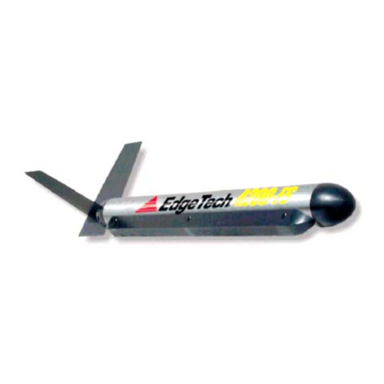
Page 13: 4200 Towfish
4 4200 TOWFISH The 4200 towfish is a hydro-dynamically stable towed body, which contains the transducers and electronics necessary to generate and receive the side scan sonar signals, and communicate with the topside unit. It is a compact stainless steel cylinder equipped with stabilizing fins and lead nose weight for hydrodynamic balance. - Page 14 A rigid tow arm is mounted on the top of the towfish just ahead of the power and telemetry connector. The tow arm provides a housing for the splice for the soft tow cable. The arm is also configured with EdgeTech’s Saf-T-Link mechanical attachment to prevent towfish loss due to snagging on the seafloor or moorings lines.
-
Page 15: Tow Cable
6 DEPLOYMENT The 4200-FS towfish may be deployed in two possible configurations depending on the users tow and handling requirements. Option 1: Standard, using a Kevlar tow cable for shallow surveys at speeds less than 8 knots. -
Page 16: Cable Attachment
FIGURE 6-2: SPARE SHEAR PINS The system is supplied with spare shear pins and retaining cotter pins. Specifications: Shear Pin: 8 mm (5/16") Delrin rod. Shear Force: 6.2 to 6.4 kN (1400-1500 lbf) 6.1.1 C ABLE TTACHMENT The tow arm and tow cable attachments are shown below. Shear Pin SafeT release catch cable... - Page 17 (2, 3 & 4). The cable is retained in the tow arm using tie wraps (2 & 3) Note: The maximum recommended tow speed using the supplied Edgetech coaxial Kevlar cable is 8 knots.
-
Page 18: Option 2 (Steel Armored Tow Cable )
2 (S PTION TEEL RMORED OW CABLE This option is used with the standard Edgetech tow-arm, as in Section 6.1 Higher speeds and depths maybe achieved using an armored tow cable. 6.2.1 C ABLE TTACHMENT Tow cable attachment arrangements as follows. -
Page 19: Troubleshooting & Repair
Once the problem area is isolated, the defective item should be replaced and returned to EdgeTech for disposition. It is recommended that a complete set of spare boards and replaceable subassemblies be kept onboard or at a readily accessible service center or depot facility. -
Page 20: Electronics Assembly Removal
lightly coated with silicone grease. Do not pack female connectors with grease unless the system is to be put in long term storage. 7.1.3 E LECTRONICS SSEMBLY EMOVAL The electronics assembly is accessed from the aft section of the towfish body. This should be done only in a clean, dry location. - Page 21 Figure 7-1: Figure 7-2: Figure 7-3: Page 13 Document: 990-0000046-1000...
-
Page 22: Transducer Removal
7.2 T ROUBLESHOOTING The 4200-FS towfish is a computer controlled device. Therefore in order to troubleshoot such a complex piece of equipment to a sub-module level, one must have the proper test equipment and thorough knowledge of the unit’s electrical operation plus hardware aspects. The purpose of this section is not to develop those techniques nor provide a step-by-step procedure where one may start and end up at the point of failure. -
Page 23: General Troubleshooting
The early sonars were driven with a high-powered energy burst similar to hitting a bell with a hammer. The 4200-FS transducers are driven with a smooth rising lower power signal that matches the transducer response. Because of this, there is no pronounced clicking noise emanating from the 4200’s transducers when they are firing. -
Page 24: Sonar Processor And Data Link
2 to 3 kHz means that self-test has failed. These tones are generated in the 4200-FS towfish and replicated on the surface when an EdgeTech topside processor is used to access the Towfish computer subsystem using the Remote Desktop application. The Self Test PASS tones repeat until data linkup has occurred between the topside Discover software, and towfish. -
Page 25: Data Link
Data throughput rates on the uplink (fish to topside) can be critical in getting smooth data from the towfish. The data throughput rate can be checked using Edgetech supplied utilities at each end of the link The SockBlast application is used to test network throughput between the 4200FS fish and the topside computer. - Page 26 Preliminary When the electronics has been removed: 1. Check that all boards are still secured to their mountings. 2. Check the mating of all connectors 3. Check that the terminal board screw connections are tight 4. Check for obvious hot /burn spots by sight and smell. No Sonar Data If the sonar display doesn’t scroll, use the ‘scope sniffing’...
-
Page 27: Tow Cables
2. SSB Board There are two LED’s of interest. ‘LED A’ flashes when 120 kHz is transmitting. ‘LED B’ flashes when 410 kHz is transmitting. 3. SIB Board There are four LED’s of interest. They have the following status when the system is operating properly. - Page 28 2. Short the two connector pins (or wires if un-terminated) of the shorted pair at both ends and measure the total resistance between the ends. R1+R2 =_______________ 3. Remove the shorts. 4. Measure the resistance between a shorted pair on one end with an ohmmeter on the Rx1 scale.
-
Page 29: Repair
Caution Prior to cutting the cable for any of the above reasons, a careful visual examination should be made for any signs of physical damage. With both ends disconnected, the tow cables should measure between 100 Mega-ohms and infinity between conductors with a 500 VDC Meg ohmmeter. When using a Simpson 260 Multi- meter, all cables wire-to-wire or wire-to-shield should measure infinity. -
Page 30: Troubleshooting Guide
ROUBLESHOOTING UIDE There are two alternatives in operating the 4200-FS towfish. One is to use the full topside compliment and a test tow cable. This is the best configuration. If a topside processor is unavailable or out of commission an external keyboard, mouse and video monitor can be attached to the towfish CPU card. - Page 31 Monitor the data link light. There should be the tow cable connections and cable-select one on the topside and towfish modem cards. jumper. Some topside processors have an indicator on Another source of an erratic link up is the AC their front panels.
- Page 32 Monitor towfish heading on sonar processor Replace compass module if heading doesn’t screen (if configured). Rotate towfish and change. verify that heading reading follows the Reorient compass module if heading change towfish orientation. doesn’t follow the direction of the towfish change.
-
Page 33: Pre-Deployment Rub Test
Possible Trouble Area(s) Perform the following test sequence to verify array switching logic and receiver hardware. These tests require operation from a system running the EdgeTech ‘Discover’ sonar- processing software. 1. High-Frequency Test: Set system to HDM mode, Set Discover Range to 100m. and on-... -
Page 34: Deployment Tests When Operational
7.4.3 D EPLOYMENT ESTS WHEN PERATIONAL Test Possible Trouble Area(s) Random irregular white lines occur in the Wet-end tow cable connector across-track data Any cable and connection in the tow cable line Water in the towfish Check data link Banding in the along-track record. Recalibrate towfish. - Page 35 FIGURE 7-4: T OWFISH OMPONENT OCATIONS Page 27 Document: 990-0000046-1000...
- Page 36 7-5: T IGURE IMENSIONS Page 28 Document: 990-0000046-1000...
- Page 37 7-6: E IGURE RANSDUCER ONNECTIONS Page 29 Document: 990-0000046-1000...
-
Page 38: Tow Cables And Connections
8 TOW CABLES AND CONNECTIONS 8.1 4200 T ELEMETRY The telemetry system uses 2 conductors for both power and telemetry signals. It is normal to use a coaxial cable for this tow connection, but for short cable lengths (typically less than 3- 500m,) a twisted pair cable may suffice. - Page 39 8-2: T 566P IGURE OW CABLE WITH TOPSIDE TERMINATION Page 31 Document: 990-0000046-1000...
-
Page 40: Armored Tow Cable Termination
8.2 A RMORED OW CABLE ERMINATION REVISIONS 8-3: A IGURE RMORED ABLE ERMINATION Page 32 Document: 990-0000046-1000... -
Page 41: 4200-Fs Towfish Parts List
9 4200-FS TOWFISH PARTS LIST DUMMY,6PIN,F,WET-MATEABLE 067-F006D00-1000 CONN,6PIN,M,BULKHEAD,4200 / MPX 067-M006B00-1000 COTTER PIN,SS316,3/32" 100-0000086-1000 SCREW,PH FH,18-8SS,M4X0.7X10MM 101-M4FH010-1316 SCREW,LSH,18-8SS,M5X0.8X10MM 101-M5LH010-1316 SCREW,BH,18-8SS,M6X1X20MM 101-M6BH016-1316 SCREW,BH,316SS,M6X1X45MM 101-M6BT045-1316 SCREW,SET,18-8SS,M8X1.25X20MM 101-M8CP020-1316 WASHER,FLAT,316SS,M5 102-M5FLTWS-1316 NUT,LOCK,18-8SS,M5X0.8 102-M5LCKNT-1316 WASHER,LOCK,316SS,M5 102-M5LCKWS-1316 WASHER,FLAT,316SS,M6 102-M6FLTWS-1316 NUT,LOCK,HEX,18-8SS,M6X1 102-M6LCKNT-1188 SHACKLE,4200 191779 CLEVIS,PIN,3/8"X1",SS 316 194867 PIN,COTTER,5/32"X1",SS316... -
Page 42: Returned Material Authorization
It is acceptable to combine the proforma invoice and packing list as long as the contents of each carton are clearly numbered and identified on the invoice. 4. Small items can be shipped prepaid directly to EdgeTech by FedEx, DHL, UPS, Airborne, etc. - Page 43 AGNETOMETER PTION INTEGRATION TO MAGNETOMETERS EdgeTech provides an optional interface to magnetometers for its Full Spectrum side scan systems, models 4200-FS and model 4300-MPX. The magnetometer option provides for the simultaneous gathering of the earth’s magnetic field strength along with side scan data.
- Page 44 Typically the magnetometer manufacturer will provide a tow cable 10m long with a mechanical termination to connect to the side scan tow arm. EdgeTech provides a custom tow point key for each magnetometer. The tow key is attached to the side scan tow arm through a sacrificial shear pin.
- Page 45 Magnetometer Option Restrain Mag Data Cable with Cable tie at this point Shear Pin Anchor Tow cable, 2 points, with cable tie Fig 3: Connection Setup for Marine Magnetics SeaSPY Magnetometer Document #: A958614 Page 3...
- Page 46 Magnetometer Option Fig 4: Connection Assembly for SeaSPY Magnetometer Document #: A958614 Page 4...
- Page 47 2. E LECTRICAL NTERFACE The electrical interface between the 4200-FS or 4300-MPX and the SeaSPY or the G-882 is via an 8-pin Micro Subconn connection (MCIL8F/MCBH8M). The RS-232 interface is setup for 9600 baud, 8 bits, 1 stop, no parity.
- Page 48 UNLESS AS MAY BE OTHERWISE PROVIDED BY CONTRACT, THESE DRAWINGS AND SPECIFICATIONS ARE THE PROPERTY DESCRIPTION DATE APPROVED OF "EDGETECH" AND ARE ISSUED IN STRICT CONFIDENCE AND SHALL NOT BE REPRODUCED, COPIED OR USED AS THE Initial Release 2005-1-5 BASIS FOR THE MANUFACTURE OR SALE OF APPARATUS WITHOUT PERMISSION. COPYRIGHT @ 2001 EDGETECH INC.
- Page 49 Magnetometer Option The EdgeTech telemetry allow for a full bi-directional communication link between the topside and the magnetometer, where data flow upstream and commands flow downstream. To properly relay the ‘Mag’ data from the towfish onto the PC/laptop running the magnetometer acquisition software, the SONAR program running in the tow fish as well as the DISCOVER software running on the topside need to be configured properly.
- Page 50 Magnetometer Option Adding a Magnetometer Customers whom wish to add a magnetometer to their current 4200-FS or 4300-MPX systems need to order an interface kit from EdgeTech as well as the magnetometer manufacturer. The EdgeTech kit consists of: 1. Breakaway key, part number 350-B980313-0300 for Geometrics or part number 350- B980314-0300 for Marine Magnetic 2.
Need help?
Do you have a question about the 4200-FS and is the answer not in the manual?
Questions and answers