
Subscribe to Our Youtube Channel
Related Manuals for Edgetech 3200-XS


Summary of Contents for Edgetech 3200-XS
- Page 1 3200-XS Sub-Bottom Profiling System User’s Manual Document No. 990-0000026-1000, Rev. 2.3 EdgeTech 4 Little Brook Road West Wareham, MA 02576 Tel: (508) 291-0057 Fax: (508) 291-2491 www.edgetech.com...
- Page 2 EdgeTech. Any reproduction of EdgeTech supplied software or file sharing is strictly prohibited.
-
Page 3: Warning-Read This First
Warning—Read This First! All personnel involved with the installation, operation or maintenance of the equipment described in this manual should read and understand the warnings and recommendations provided below. Static Sensitive Devices This equipment contains devices that are extremely sensitive to static electrical charges. Therefore extreme care should be taken when handling them as static electricity may be present on the body and clothing. -
Page 4: Preface
Preface We, the employees at EdgeTech, would like to thank you for purchasing a 3200-XS Sub-Bottom Profiling System. At EdgeTech it is our policy to provide high quality, cost effective products and support services that meet or exceed your requirements, to deliver them on time and to continuously look for ways to improve them. -
Page 5: Warnings, Cautions And Notes
Liability EdgeTech has made every effort to document in this manual the 3200-XS Sub-Bottom Profiling System accurately and completely. However, EdgeTech assumes no liability for errors or for any damages that result from the use of this manual or the equipment it documents. -
Page 6: Warranty
Warranty repair will be done by EdgeTech free of charge. Shipping costs are to be borne by the customer. Malfunction due to improper use is not covered in the warranty and EdgeTech disclaims any liability for consequential damage resulting from defects in the performance of the equipment. -
Page 7: Software Service Agreement
Furthermore, EdgeTech software upgrades are meant for the sole use of EdgeTech customers that have purchased a system within a year or have an existing SSA. Any reproduction of EdgeTech supplied software or file sharing is strictly prohibited. -
Page 8: Software Telephone, Facsimile And E-Mail Support
The SSA entitles EdgeTech customers to contact EdgeTech Customer Service by telephone, facsimile or e-mail to report a difficulty, to discuss a problem or to receive advice on the best way to perform a task. When contacted, EdgeTech Customer Service will do the following: •... -
Page 9: Returned Material Authorization
Small items can be shipped prepaid directly to EdgeTech by FedEx, DHL, UPS, Airborne, etc. If the equipment is the property of EdgeTech (formerly EG&G Marine Instruments Division) please insure for full value. Fax one invoice, packing list, and a copy of the airway bill to EdgeTech upon shipment. -
Page 10: Customer Service
Customer Service Customer service personnel at EdgeTech are always eager to hear from users of our products. Your feedback is welcome and is a valuable source of information which we use to continually improve these products. Therefore we encourage you to contact customer service to offer any suggestions or to request technical support. -
Page 11: Table Of Contents
Table of Contents Warning—Read This First! ........iii Static Sensitive Devices . - Page 12 Connecting the Deck Unit ......3-10 3200-XS Sub-Bottom Profiling System User’s Manual...
- Page 13 ........4-1 4.1.1 Cleaning the Air Filter in the 3200-XS Topside Processor ..4-1 4.1.2 Cleaning the Tow Vehicle and Tow Cable after Use .
-
Page 14: List Of Figures
Deck Unit Front Side ..........3-5 Figure 3-3: Behind 3200-XS Topside Processor Access Panel ..... . . 3-6 Figure 3-4: A 75-Meter Kevlar Reinforced Tow Cable Shown Connected and Attached to an SB-216S Tow Vehicle . - Page 15 Deck Unit General Specifications ........2-1 Table 2-2: 3200-XS Topside Processor Specifications ......2-2 Table 2-3: Power Amplifier Specifications .
-
Page 17: Overview
The 3200-XS transmits an FM pulse (also called a "chirp pulse") that is linearly swept over a full spectrum frequency range. The reflections measured by the system are displayed as shades of gray or color on a computer monitor and may be printed on a continuous feed thermal printer. -
Page 18: Separate Acoustic Projectors And Receivers
EdgeTech technical support can provide assistance in selecting the best tow vehicle for your application. -
Page 19: High Resolution
Advantages of Full Spectrum Chirp Technology 1.2.4 High Resolution Signals received at the surface from the hydrophone arrays in the tow vehicle pass through a software controlled programmable gain amplifier before being digitized with a 16-bit analog-to-digital (A/D) converter at a sampling rate of 20, 25, 40, or 50 kHz The FM pulse is then compressed using a digital compression filter. -
Page 20: Full Spectrum Chirp Technology Applications
SECTION 1: Overview Full Spectrum Chirp Technology Applications Applications for the Full Spectrum Chirp Technology used in the 3200-XS Sub-Bottom Profiling System are many and include the following: EEZ resource development • Imaging fluidized mud to a resolution of 8 cm •... -
Page 21: Main System Components
1.4.1 Deck Unit The Deck Unit is shown in Figure 1-1 and consists of a 3200-XS Topside Processor and a 2-kW Power Amplifier mounted in a portable 19-inch rack type enclosure and shipped in a heavy duty reusable transport case. The processor and the amplifier can also be removed and mounted in any standard 19-inch rack. -
Page 22: Figure 1-2: Tiger And Mother Boards Inside 3200-Xs Topside Processor
Tiger board, refer to “Tiger Board Description” on page 1-9. The Deck Unit also includes the EdgeTech DISCOVER 3200SB software preinstalled on the 3200-XS Topside Processor. DISCOVER 3200SB is a data acquisition and processing program designed exclusively for EdgeTech Full Spectrum chirp sonar systems. The... -
Page 23: Sb-424, Sb-216S And Sb-512I Tow Vehicles
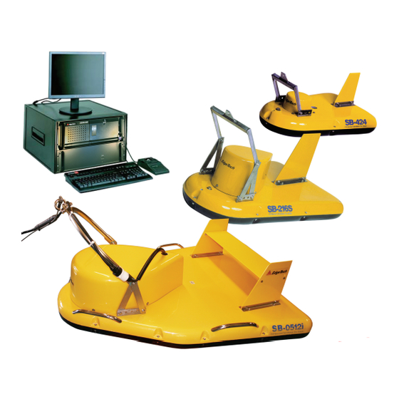
Main System Components 1.4.2 SB-424, SB-216S and SB-512i Tow Vehicles The SB-424, SB-216S and SB-512i Tow Vehicles are each designed to operate over a specific frequency range, and as lower operating frequencies generally require longer hydrophone arrays and larger transducers, they differ primarily in size and weight. The SB-424 Tow Vehicle, which is the smallest of the three, operates over a frequency range of 4–24 kHz, followed by the SB-216S at 2–16 kHz and then the SB-512i at 0.500–12 kHz. -
Page 24: Figure 1-4: Sb-424, Sb-216S And Sb-512I Tow Vehicles
SECTION 1: Overview SB-424 Tow Vehicle SB-216S Tow Vehicle SB-512i Tow Vehicle Figure 1-4: SB-424, SB-216S and SB-512i Tow Vehicles 3200-XS Sub-Bottom Profiling System User’s Manual Doc. No. 990-0000026-1000, Rev. 2.3... -
Page 25: Tiger Board Description
Tiger Board Description Tiger Board Description The Sonar Interface board (Tiger board) is the real-time controller for sonar processing. It includes transmit waveform tables and multiple channels of 10-bit high speed digital-to-analog (D/A) converters, support for external and internal triggers, and support for multiple sonar analog-to-digital (A/D) converters. -
Page 26: Figure 1-5: Tiger Board Set
1-10 SECTION 1: Overview Carrier board Acquisition board Sonar IDE board Figure 1-5: Tiger Board Set 3200-XS Sub-Bottom Profiling System User’s Manual Doc. No. 990-0000026-1000, Rev. 2.3... -
Page 27: Specifications
All specifications are subject to change without notice. NOTE: Deck Unit The Deck Unit includes the 3200-XS Topside Processor and the Power Amplifier in a 19-inch rack type enclosure. CAUTION! The Deck Unit is application specific. It should not be used for purposes other than that for which it was intended. -
Page 28: 3200-Xs Topside Processor
SECTION 2: Specifications 2.1.2 3200-XS Topside Processor The specifications for the 3200-XS Topside Processor are shown in Table 2-2. Table 2-2: 3200-XS Topside Processor Specifications Mother board: Intel Pentium 4 Sonar Interface: Sonar Interface board (Tiger board) composed of Carrier board, Acquisition... -
Page 29: Power Amplifier
SB-424, SB-216S and SB-512i Tow Vehicles 2.1.3 Power Amplifier The specifications for the Power Amplifier are shown in Table 2-3. Table 2-3: Power Amplifier Specifications Number of channels: Gain: 33 dB/channel Output power: 2000 W peak Input voltage: 120–220 VAC, 50/60 Hz, manually selectable SB-424, SB-216S and SB-512i Tow Vehicles The general specifications for the SB-424, SB-216S and SB-512i Tow Vehicles are shown in Table 2-4. - Page 30 (approximately 750 m/s). For example, a full bandwidth pulse from an SB-424 Tow Vehicle has a vertical resolution of 3.75 cm (1/20,000 x 750). 3200-XS Sub-Bottom Profiling System User’s Manual Doc. No. 990-0000026-1000, Rev. 2.3...
-
Page 31: 75-Meter Kevlar Reinforced Tow Cable
75-Meter Kevlar Reinforced Tow Cable b. The value for sub-bottom penetration is the maximum distance beneath the sea floor that a step change of 10% in density can be seen on the sub-bottom display. This assumes that the sediment is gas free (no organic materials), that the lowest frequency of the pulse spectrum is transmitted and that the vehicle is within 5 meters of the seabed (range for maximum penetration). -
Page 33: Setup And Test
Report any damage to the carrier and to EdgeTech. If the shipping containers appear free of damage, carefully unpack the components and inspect them for damage. Also check the packing list and verify that all the items on the list are included. -
Page 34: Power Requirements
SECTION 3: Setup and Test Power Requirements The system power requirements are 120–220 VAC, 50/60 Hz. For the 3200-XS Topside Processor, the input voltage is auto sensing. For the Power Amplifier you must select 120 VAC or 220 VAC operation manually. -
Page 35: Locating The Deck Unit
Figure 3-1 and Figure 3-2. Several test points are also provided for voltage measurements. The 3200-XS Topside Processor controls, along with a DVD R/W drive and a 3.5-inch are located behind an access panel as shown in Figure 3-3 on page 3-6. -
Page 36: Figure 3-1: Deck Unit Back Side
COM 1-NAV PARALLEL POWER connector connector SUPPLY MONITOR COM3 ETHERNET switch connectors connector connector connector TRIGGER IN connector TRIGGER OUT connector READY (left) and Ping (right) indicators POWER AMP OUT TX1 indicator POWER AMP OUT TX2 indicator 12 VDC OUT TO PREAMP test point AC POWER... - Page 37 Access panel (see SYSTEM HARD DISK indicator indicator Figure 3-3 on page 3-6) USB connector TRACKBALL connector KEYBOARD connector POWER switch Figure 3-2: Deck Unit Front Side...
- Page 38 POWER switch RESET switch 3.5-inch floppy drive Figure 3-3: Behind 3200-XS Topside Processor Access Panel POWER AMP OUT TX2: Red indicator. Flashes when Channel 2 of the Power Amplifier transmits. READY: Red indicator. Illuminates when the system is ready to transmit. On power up it will take one to two minutes for the indicator to illuminate.
-
Page 39: Deck Unit Connections
Deck Unit Connections Deck Unit Connections Most of the connections to the Deck Unit are made using connectors on the back. These connectors are shown in Figure 3-1 on page 3-4. The trackball and keyboard connections are made using connectors on the front of the Deck Unit. They are shown in Figure 3-2 on page 3-5. -
Page 40: Connecting The System Components
SECTION 3: Setup and Test Connecting the System Components All of the 3200-XS Sub-Bottom Profiling System components, including optional components, such as a printer, a navigation system, and external sonar systems, are made to the Deck Unit. WARNING! Do not connect the tow cable to the Deck Unit before connecting it to the tow vehicle, otherwise injury or death can occur if the exposed connector on the tow cable is energized. -
Page 41: Figure 3-4: A 75-Meter Kevlar Reinforced Tow Cable Shown Connected And Attached
Connecting the System Components Cable grip eyelet Shackle Tow bridle Stainless steel cable for strain relief Tie wrap 75-Meter Kevlar Reinforced Tow Cable Tow vehicle tow cable connector Cable grip Figure 3-4: A 75-Meter Kevlar Reinforced Tow Cable Shown Connected and Attached to an SB-216S Tow Vehicle Tow cable Tow cable... -
Page 42: Connecting The Deck Unit
If a navigation system is to be used, connect the navigation system output to the COM 1-NAV connector. If an external source is to be used to trigger the 3200-XS Sub-Bottom Profiling System, connect the trigger output of this source to the TRIGGER IN connector. -
Page 43: Activating The System
Turn on the POWER switch on the Power Amplifier. Turn on the SYSTEM POWER switch on the 3200-XS Topside Processor. The SYSTEM indicator on the 3200-XS Topside Processor should illuminate and remain on, and the HARD DISK indicator should flash for two to three minutes while a self test is run. -
Page 44: Figure 3-6: The Discover 3200Sb Main Window
3-12 SECTION 3: Setup and Test Figure 3-6: The DISCOVER 3200SB Main Window Figure 3-7: The Options Dialog Box, Sonar Control Tab 3200-XS Sub-Bottom Profiling System User’s Manual Doc. No. 990-0000026-1000, Rev. 2.3... -
Page 45: Tow Vehicle Deployment
The SB-424, SB-216S and SB-512i Tow Vehicles can be towed using the 75-Meter Kevlar Reinforced Tow Cable that is available separately with the 3200-XS Sub-Bottom Profiling System. However, it is recommended that a steel cable with a minimum 500 Kg (1100 lb) working strength be used instead of this tow cable to tow the larger SB-0512i vehicle. -
Page 46: Obtaining The Best Sonar Imagery When Towing
-1 dB beam width should be at least 10 degrees at 6 kHz. For this pulse and receiving array, the -1 dB beam width at 6 kHz is about 7 degrees, or 4 degrees x 10 kHz/6 kHz = 6.6 degrees. 3200-XS Sub-Bottom Profiling System User’s Manual Doc. No. 990-0000026-1000, Rev. 2.3... - Page 47 3-15 Tow Vehicle Deployment Therefore only reflection coefficient measurements made when the sea floor slope is within 3.5 degrees of horizontal will be accurate within 10% (1 dB). The attitude of the tow vehicle with respect to the horizontal plane must meet the -1 dB criteria described above for sediment classification surveys.
-
Page 49: Maintenance And Troubleshooting
However, most of the maintenance is performed after each deployment and recovery cycle of the tow vehicle. Other maintenance, such as cleaning of the air filter in the 3200-XS Topside Processor, can be performed as necessary. -
Page 50: Inspecting And Cleaning The Underwater Connectors
4.1.4 Storage When not in use, all the components of the 3200-XS Sub-Bottom Profiling System should be packed in their original shipping containers in the same manner in which they were originally shipped and stored in a dry area. -
Page 51: Disassembling And Reassembling A Tow Vehicle
Disassembling and Reassembling a Tow Vehicle Disassembling and Reassembling a Tow Vehicle The procedures below describe how to disassemble and reassemble a tow vehicle to access the transducers, hydrophones, transformers, inductors, spider boxes, spider arrays, and preamplifiers. The tools required are a socket wrench, 7/16 and 1/2-inch sockets, and a small flat screw driver. - Page 52 Spider array Transformer SB-512i Tow Vehicle Spider box (Part of KT-216A2) Figure 4-3: SB-424, SB-216S and SB-512i Tow Vehicle Transducers, Hydrophones, Transformers, Inductors, Spider Boxes, Spider Arrays, And Preamplifiers 3200-XS Sub-Bottom Profiling System User’s Manual Doc. No. 990-0000026-1000, Rev. 2.3...
-
Page 53: Figure 4-5: Removing The Teardrop Cover
Disassembling and Reassembling a Tow Vehicle Using the socket wrench Teardrop with the 7/16-inch socket, cover remove all the bolts securing the teardrop cover to the body of the tow 7/16-inch vehicle as shown in bolt Figure 4-4. Socket wrench Tow vehicle body Figure 4-4: Removing the 7/16-Inch Bolts Securing... -
Page 54: Reassembling The Tow Vehicle
Nuts Securing the Top Cover of the Tow Vehicle Body 4.3.2 Reassembling the Tow Vehicle To reassemble the tow vehicle reverse the disassembly procedure described in “Disassembling a Tow Vehicle” on page 4-3. 3200-XS Sub-Bottom Profiling System User’s Manual Doc. No. 990-0000026-1000, Rev. 2.3... -
Page 55: Troubleshooting
The Deck Unit is plugged into an appropriate AC power source (see • “Power Requirements” on page 3-2). The AC cables inside the Deck Unit are plugged into the 3200-XS Topside • Processor and the Power Amplifier and to the AC power outlet. - Page 56 BRIDGE and The tow vehicle cable harness Verify that all the cable harness connections are loose. connectors in the tow vehicle are properly mated. 3200-XS Sub-Bottom Profiling System User’s Manual Doc. No. 990-0000026-1000, Rev. 2.3...
- Page 57 Unit. This voltage should be 12 VDC. If 12 VDC is not present, verify that it is present on the Tiger board in the 3200-XS Topside Processor. If 12 VDC is not present on the Tiger board, repair or replace the Tiger board.
- Page 58 3 to 5 knots. The tow vehicle is being towed too Lower the speed of the tow fast. vehicle. 3200-XS Sub-Bottom Profiling System User’s Manual Doc. No. 990-0000026-1000, Rev. 2.3...
-
Page 59: Connector Pinouts
4-11 Connector Pinouts Connector Pinouts Pinout information is provided for the SEA CABLE connector on the back of the Deck Unit in Figure 4-8 and Table 4-2, and the tow vehicle tow cable connector in Figure 4-8 and Table 4-3. Table 4-2: SEA CABLE Connector Pinouts... -
Page 60: Wiring And Connector Pinout Drawings
Maintenance and Troubleshooting Wiring and Connector Pinout Drawings Listed in Table 4-4 and included in the following pages are the 3200-XS Sub-Bottom Profiling System wiring and connector pinout drawings for the Deck Unit and the SB-424, SB-216S and SB-512i Tow Vehicles. For the Deck Unit a wiring harness diagram and connector pinout information are provided. -
Page 69: Printer Connections
EPC Model 1086 • EPC Model HSP-100 • Raytheon Model TDU-850 • Listed in Table A-1 are the required settings to properly interface a printer with the 3200-XS Sub-Bottom Profiling System. Table A-1: Printer Setting Requirements Trigger: Internal Data input:... -
Page 70: A.1 Epc Model 1086
Paper/film width: 25.6 cm (10.0 in.) Resolution: 8 dots/mm (203 dots/in.) Tone shades: Up to 256 gray scale Interface: 8 bit parallel Plot speed: 10 ms per line maximum 3200-XS Sub-Bottom Profiling System User’s Manual Doc. No. 990-0000026-1000, Rev. 2.3... -
Page 71: Raytheon Model Tdu-850
Raytheon Model TDU-850 A.3 Raytheon Model TDU-850 The Raytheon Model TDU-850 printer is a high speed gray shade printer that uses a fixed thermal head to produce a hard copy image on direct recording thermal paper. The general specifications for the Model TDU-850 printer are listed in Table A-4. Table A-4: Raytheon Model TDU-850 General Specifications Paper width:... -
Page 73: Frequently Asked Questions
20-gauge wire and are used for the received signal, 12 VDC, common, and a spare. Can a Rochester 301301 (3 core coax) armored cable be used? A 500-meter maximum length armored cable can be used. Contact EdgeTech for the wiring recommendation. - Page 74 APPENDIX B: Frequently Asked Questions How does the 3200-XS Sub-Bottom Profiling System interface to a navigation device? The COM 1-NAV or the COM3 RS-232 serial port can be used to interface with a navigation device. How do the environmental conditions affect the performance of the 3200-XS...
Need help?
Do you have a question about the 3200-XS and is the answer not in the manual?
Questions and answers