Sign In
Upload
Manuals
Brands
Edgetech Manuals
Marine Equipment
3400
Edgetech 3400 Manuals
Manuals and User Guides for Edgetech 3400. We have
3
Edgetech 3400 manuals available for free PDF download: User Hardware Manual, Quick Start Manual
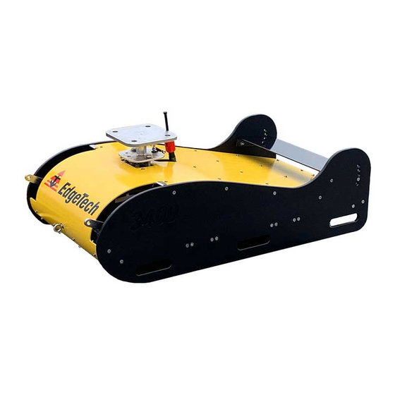
Edgetech 3400 User Hardware Manual (122 pages)
Sub-Bottom Portable System
Brand:
Edgetech
| Category:
Marine Equipment
| Size: 6 MB
Table of Contents
Attention - Read this First
3
Warnings, Cautions, and Notes
3
Hardware Variations and Compatibility
4
About this Document
5
Liability
5
Revision History
5
Warranty Statement
6
Software Service Overview
7
Software Updates and Enhancements
7
Returned Material Authorization
8
RMA Purpose
8
Customer Service
9
Company Background
10
Table of Contents
11
Table of Contents
16
List of Figures
16
List of Tables
21
Overview
21
Key Features of the 3400 Sub-Bottom Profiling System
21
CHIRP Transmission
21
Advantages of Full Spectrum CHIRP Technology
22
Dual Wideband Transmitters
24
Dual Frequency Transmission
24
Figure 1-1: 3400 Sub-Bottom Transducers
24
Figure 1-2: Discover 3400 High (Yellow) and Low (Blue) Sub-Bottom Displays
24
Enhanced Sub-Bottom Multi-Channel PVDF Receiver
25
Figure 1-3 3400 PVDF Receiver
25
Figure 1-4: Traditional Hydrophone with Side-Lob Echoes
25
Figure 1-5: 3400 PVDF Imagery Side Lobes with Reduced Echoes
26
Figure 1-6: Comparison of 3400 Vs. Traditional Line Arrays over same Survey Line
26
Reflection Coefficient Calculation
27
Sub-Bottom of "Pipeliner" Mode
27
Figure 1-7: Pipeliner Mode Diffraction
28
Figure 1-8: Diffraction Hyperbolas in the Echo Data
28
Surface Echo Attenuation
29
Pulse Library Tailored for most Survey Applications
29
Built-In Motion, Pitch, Roll, Heave, and Depth Sensors
29
3400 Applications
29
Main System Components
29
3400 Rack Mounted Topside in Case and Ruggedized Laptop
30
3400 Cable
30
3400 Standard Towfish
30
Figure 1-9: Deployed 3400 Rackmount System
30
Figure 1-10: Tow Cable
30
3400 Tow Vehicle Pole Mounting Kit
31
Figure 1-11: 3400 Towfish Forward View
31
Figure 1-12: 3400 Towfish Aft View
31
Figure 1-13: 3400 Towfish Port View
31
3400 Options
32
3400 OTS (Over-The-Side) Vehicle Option
32
Figure 1-14: 3400 Towfish with Pole Mounting Flange Installed
32
Figure 1-15: Side View of 3400 OTS Vehicle Configuration Option
32
Amplifier Option
33
Figure 1-16: Forward View of 3400 OTS Vehicle Configuration Option
33
Figure 1-17: 3400 System with Amplifier in Cases
33
Figure 1-18: Amplifier in Case
33
Specifications
34
3400 Vehicle Specifications
34
3400 Sonar Specifications
34
3400 Towfish Standard 2-16 Khz Sonar Specifications
34
3400 OTS 1-10 Khz Sonar Specifications
34
3400 Vehicle Physical Specifications
34
3400 Standard Towfish
34
Table 2-1: 3400 Standard Sonar Specifications
34
Table 2-2: 3400 OTS Sonar Specifications
34
3400 OTS Specifications
35
3400 Topside Specifications
35
3400 Topside Physical Specifications
35
Table 2-3: 3400 Standard Towfish Specifications
35
Table 2-4: 3400 OTS Vehicle Specifications
35
3400 Topside Electrical Specifications
36
Edgetech Laptop Computer Specifications
36
Table 2-5: 3400 Topside General Specifications
36
Table 2-6 3400 Topside Specifications
36
Amplifier Option Physical Specifications
37
Amplifier Option Electrical Specifications
37
3400 Kevlar Tow Cable Specifications
37
Table 2-7: Topside Computer Specifications
37
Table 2-8: Amplifier Option Physical Specifications
37
Table 2-9: Amplifier Option Electrical Specifications
37
Table 2-10: 50-Meter Tow Cable Specification
38
Mechanical Drawings
39
3400 Standard Towfish ICD
39
Figure 2-1: 3400 Towfish ICD (Click Image to Open Attached PDF)
39
3400 Standard Towfish with Pole Mounting Hardware
40
Figure 2-2: 3400 Towfish with Pole Mounting Hardware ICD (Click Image to Open Attached PDF)
40
3400 OTS Vehicle ICD
41
Figure 2-3: 3400 OTS Vehicle ICD (Click Image to Open Attached PDF)
41
3400 Topside ICD
42
Figure 2-4: 3400 Topside ICD (Click Image to Open Attached PDF)
42
3400 Topside Case ICD
43
Figure 2-5 3400 Topside Case ICD (Click Image to Open Attached PDF)
43
3400 Pole Mount Plate ICD
44
Figure 2-6: 3400 SBP Pole Mounting Plate ICD
44
3400 OTS Mounting Flange ICD
45
Figure 2-7: 3400 OTS Vehicle Mounting Flange
45
3400 Technical Descriptions
46
3400 Standard Towfish Technical Description
46
Figure 3-1: Bottom of Standard 3400 System
46
3400 Standard System Connection Diagram
47
Figure 3-2: 3400 System Connection Diagram
47
3400 Standard Towfish Electronics Bottle and End Cap Diagrams
48
Figure 3-3: 3400 Electronics Bottle ICD
48
Figure 3-4: Sonar Processor Endcap Diagram
49
Figure 3-5: 3400 Electronics Bottle Pinouts
50
3400 Standard Towfish Cable and Connector Diagrams
51
Figure 3-6: Sub Cable T Splice 3400 SBP Tow Cable to Bottle, Transformer, and Tow Cable
51
Figure 3-7: 3400 SBP 50 Meter Tow Cable
52
Figure 3-8: 3400 SBP 50 Meter Tow Cable
53
Figure 3-9: Tow Cable to Tow Fish Pinouts (Wet End)
54
3400 Portable Topside Technical Description
55
3400 Topside Controls, Indicators, and Connectors
55
Figure 3-10: 3400 Topside Front Panel
55
Table 3-1: 3400 Topside Front Panel Indicator Light and Switch Descriptions
55
3400 Amplifier Option Technical Description
56
Figure 3-11: 3400 Topside Rear Panel
56
Figure 3-12: Amplifier Front Panel
56
Table 3-2: 3400 Topside Back Panel Switches and Connections
56
Figure 3-13: Back Panel Amplifier and Connector Panel
57
Table 3-3: Amplifier Front Panel Controls and Indicator Lights
57
Table 3-4: Amplifier Connector Panel Connections
57
Table 3-5: Back Panel Amplifier Connections
57
Amplifier Rack Mount
58
Figure 3-14: Amplifier Rack Mount ICD (Click Image to Open Attached PDF)
58
Figure 3-15: Amplifier Back Panel Interface to 3400
59
Amplifier Connection Diagram
60
Figure 3-16: Amplifier Connection Diagram (3400 OTS Vehicle Variant Depicted- Connections Are the same Regardless of Variant)
60
Amplifier Cable Diagram
61
Figure 3-17: Amplifier to 3400 Topside Interface Cable
61
3400 OTS (Over-The-Side) Technical Description
62
Figure 3-18: Bottom of 3400 OTS Vehicle
62
3400 OTS Option Connection Diagram
63
Figure 3-19: 3400 OTS Option Connection Diagram
63
3400 OTS Electronics Bottle
64
Figure 3-20: 3400 OTS Electronics Bottle (same as Standard 3400)
64
Figure 3-21: 3400 OTS Electronics Bottle Endcap
65
Figure 3-22: 3400 OTS Pinouts
66
3400 OTS Vehicle Cable and Connector Diagrams
67
Figure 3-23: Sub Cable T Splice 3400 OTS Tow Cable to Bottle, Transformer, and Tow Cable
67
Figure 3-24: 3400 OTS 50 Meter Tow Cable
68
Figure 3-25: 3400 OTS 50 Meter Tow Cable
69
Figure 3-26: Tow Cable to Tow Fish Pinouts (Wet End)
70
Setup and Activation
71
Standard 3400 Towfish Setup and Activation
71
Unpacking and Inspection
71
Power Requirements
72
Use of an Uninterruptable Power Supply
72
Changing to a Non-US Power Plug
72
Navigation Interface
72
Table 4-1: AC Power Cord Wiring
72
3400 Portable Topside Placement
73
Connecting the System Components
73
Figure 4-1: 3400 Topside Serial Port Navigation Connection
73
Connecting and Attaching the Tow Cable to the Tow Vehicle
74
3400 Portable Topside Connection and Activation
74
Connecting 3400 System Components
75
Figure 4-2: 3400 System Connections
75
Connecting 3400 Systems Components and Optional Amplifier
76
Making an Ethernet Connection
76
Activating the System
77
Figure 4-3: 3400 Network Configuration Diagram
77
Performing Sub Bottom Pre-Deployment Checks
78
Figure 4-4: 3400 Topside Front Panel-LED Indicator Lights
78
Table 4-2: 3400 LED Indicator Light Type, Color and Status
78
Figure 4-5: Discover 3400 Application Window
79
Figure 4-6: the Towfish Control Tab
79
Figure 4-7: Towfish Control Tab-Pulse and Transmit Level Called out
80
Figure 4-8: Discover Shortcut Toolbar- Range Text Field and Normalize Gain Button Called out
80
Figure 4-9: Tap Test Results
80
3400 Tow Vehicle Deployment
81
Figure 4-10: 3400 Tow Cable Grip Bridle Shackle Attachment
81
Figure 4-11: Towfish Deployment
82
Conducting Sediment Classification Surveys When Towing
83
Obtaining the Best Sonar Imagery When Towing
83
AHRS Usage
84
Towfish Layback Charts
84
Table 4-3: 3400 25-Meter with Lead Pack Installed Layback Chart
85
Table 4-4 3400 40-Meter with Lead Pack Installed Layback Chart
85
U-Hinge Tow Bridle
86
U-Hinge Tow Bridle Adjustment
86
Table 4-5: 3400 50-Meter with Lead Pack Installed Layback Chart
86
U-Hinge Tow Bridle Removal Instructions
87
Figure 4-12: Loosening Bridle Elbow
87
Figure 4-13: Bridle Stowed against Vehicle
87
Figure 4-14: Nut and Bolt Location Looking through Handhold Hole
88
Figure 4-15: Bridle Arm Bolt Locations- 2 Bolts Port and Starboard Sides
89
Figure 4-16: Bridle Removal Tool Orientation
90
Figure 4-17: Bridle Removal: Split Ring Removal
91
Figure 4-18: Bridle Removal-Elbow Hardware Removal
91
Pole Mounting the 3400 Tow Vehicle
92
Removing the Tow Bridle
92
Removing Weights
92
Figure 4-19: 3400 Towfish with Pole Mount Installed, Tow Arms, Weights, and Elevator Removed
92
Figure 4-20: 3400 Pole Mount Instruction-Front Panel Removal with (12) Screws and Eye Bolt Called out
93
Figure 4-21: 3400 Pole Mount Instruction- Weight Removal-Location of Bolt Hardware Top of Vehicle
93
Removing the Rear Elevator
94
Figure 4-22: 3400 Pole Mount Instruction- Weight Removal-Location of Bolt Heads on Bottom of Vehicle
94
Pole Mount Installation Instructions
95
Figure 4-23: 3400 Pole Mount Instruction-Elevator Hex Screw Positions
95
Figure 4-24: Port and Starboard Set Screw Removal
97
Figure 4-25: Forward Dorsal Pole Mount Cable Hole Position
97
Figure 4-26: Forward Dorsal Bolt Locking Washer and Molybdenum Disulfide Coating
98
Figure 4-27: Forward Dorsal Pole Mount Bolt Position
98
Figure 4-28: Port and Starboard Pole Mount Bolt Positions
99
Figure 4-29: Pole Mount Bolt Tightening
99
Figure 4-30: 3400 Sideview with Pole Mount Installed
100
Figure 4-31: Towfish Mounting Flange to Pole Mount Flange Bolt Assembly
101
Utilizing the Forward and Aft Eye Bolts
102
Figure 4-32: Pole Mounted 3400 System
102
3400 OTS Setup and Activation
103
3400 OTS Unpacking and Inspection
103
Figure 4-33: Forward Eye Bolt
103
Figure 4-34: Aft Eye Bolt
103
Installing Rubber U-Shaped Safety Trim
104
Power Requirements
105
Use of an Uninterruptable Power Supply
105
Figure 4-35: 3400 OTS Rubber Trim Installation
105
Changing to a Non-US Power Plug
106
Navigation Interface
106
3400 Portable Topside Placement
106
Figure 4-36: 3400 Topside Serial Port Navigation Connection
106
Table 4-6: AC Power Cord Wiring
106
Connecting the 3400 OTS System Components
107
Instructions on Running Tow Cable to Connector
107
Figure 4-37: OTS Mounting Flange, Cable Clip, and Sea Cable Connector
107
Figure 4-38: OTS Mounting Flange
108
Figure 4-39: OTS Sea Cable Connector and Clip
108
Instructions on Securing OTS Mount to Vessels Mounting Hardware
109
3400 OTS Portable Topside Connection and Activation
109
Figure 4-40: OTS Mounting Flange with Bolts Installed
109
Figure 4-41: OTS Flange Bolt Assembly
109
Performing Sub-Bottom Pre-Deployment Checks
110
3400 OTS Vehicle Deployment
110
Obtaining the Best Sonar Imagery
110
Conducting Sediment Classification Surveys When Towing
110
AHRS Usage
111
Maintenance
112
Portable Topside
112
Cleaning the Tow Vehicle and Tow Cable after Use
112
Cleaning the 3400 OTS Vehicle after Use
112
Figure 5-1: OTS Mounting Flange Recessed Structure
112
Inspecting and Cleaning the Underwater Connectors
113
Storage
113
Altering the 3400 Towfish Configuration
113
Adjusting or Removing the Rear Elevator
114
Figure 5-2: Elevator Hex Screw Positions
114
Removing the Sonar Processor Bottle
115
Figure 5-3: Electronics Bottle Cotter Pin Removal
116
Figure 5-4: Electronic Bottle Latch and Rubber Strip Locations
117
Troubleshooting
118
Computer System Restoration
118
AHRS Calibration
120
Kits
121
Table 7-1: 3400 Towfish Kit
121
Table 7-2: 3400 Topside Spares Kit
121
Table 7-3: 3400 SBP Pole Mount Kit
121
Figure 7-1: 3400 OTS Vehicle Spares Kit
122
Table 7-4: 3400 Pole-Mounting Kit
122
Advertisement
Edgetech 3400 User Hardware Manual (100 pages)
PORTABLE SUB-BOTTOM SYSTEM
Brand:
Edgetech
| Category:
Marine Equipment
| Size: 10 MB
Table of Contents
Attention - Read this First
3
Warnings, Cautions, and Notes
3
Hardware Variations and Compatibility
4
About this Document
5
Liability
5
Revision History
5
Warranty Statement
6
Software Service Overview
7
Software Updates and Enhancements
7
Returned Material Authorization
8
RMA Purpose
8
Customer Service
8
Company Background
10
Table of Contents
11
List of Figures
15
1 Overview
19
Key Features of the 3400 Sub-Bottom Profiling System
19
CHIRP Transmission
19
Advantages of Full Spectrum CHIRP Technology
20
Dual Wideband Transmitters
22
Dual Frequency Transmission
22
Figure 1-1: 3400 Sub-Bottom Transducers
22
Enhanced Sub-Bottom Multi-Channel PVDF Receiver
23
Figure 1-2: Discover 3400 High (Yellow) and Low (Blue) Sub-Bottom Displays
23
Figure 1-3 3400 PVDF Receiver
24
Figure 1-4: Traditional Hydrophone with Side-Lob Echoes
24
Figure 1-5: 3400 PVDF Imagery Side Lobes with Reduces Echoes
25
Figure 1-6: Comparison of 3400 Vs. Traditional Line Arrays over same Survey Line
25
Sub-Bottom of "Pipeliner" Mode
26
Figure 1-7: Pipeliner Mode Diffraction
26
Surface Echo Attenuation
27
Pulse Library Tailored for most Survey Applications
27
Built-In Motion, Pitch, Roll, Heave and Depth Sensors
27
Figure 1-8: Diffraction Hyperbolas in the Echo Data
27
3400 Applications
28
Main System Components
28
3400 Rack Mounted Topside in Case and Ruggedized Laptop
28
Figure 1-9: Deployed 3400 Rackmount System
28
3400 Cable
29
3400 Towfish
29
Figure 1-10: Tow Cable
29
Figure 1-11: 3400 Forward View
29
Figure 1-12: 3400 Aft View
29
3400 Pole Mounting Kit
30
Figure 1-13: 3400 Starboard View
30
Figure 1-14: 3400 Towfish with Pole Mounting Flange Installed
30
3400 Options
31
Amplifier Option
31
Figure 1-15: 3400 Pole Mounting Flange
31
Figure 1-16: 3400 System with Amplifier in Cases
31
Figure 1-17: Amplifier in Case
31
2 Specifications
32
Towfish Specifications
32
3400 Sonar Specifications
32
3400 Towfish Physical Specifications
32
Table 2-1: Sonar Specifications
32
Table 2-2: Towfish Specifications
32
3400 Topside Specifications
33
3400 Topside Physical Specifications
33
3400 Topside Electrical Specifications
33
Table 2-3: 2300 Rackmount General Specifications
33
Table 2-4 3400 Topside Specifications
33
Edgetech Laptop Computer Specifications
34
Amplifier Option Physical Specifications
34
Amplifier Option Electrical Specifications
34
Table 2-5: Topside Computer Specifications
34
Table 2-6: Amplifier Option Physical Specifications
34
Table 2-7: Amplifier Option Electrical Specifications
34
3400 Kevlar Tow Cable Specifications
35
Table 2-8: 50-Meter Tow Cable Specification
35
Mechanical Drawings
36
3400 Towfish ICD
36
Figure 2-1: 3400 Towfish ICD
36
3400 Topside ICD
37
Figure 2-2: 3400 Topside ICD
37
3400 Topside Case ICD
38
Figure 2-3 3400 Topside Case ICD
38
3400 Pole Mount Flange ICD
39
Figure 2-4: Pole Mount Flange
39
3400 Technical Descriptions
40
Towfish Technical Description
40
Figure 3-1: Bottom of Standard 3400 System
40
3400 System Connection Diagram
41
Figure 3-2: 3400 System Connection Diagram
41
Electronics Bottle and End Cap Diagrams
42
Figure 3-3: 3400 Electronics Bottle ICD
42
Figure 3-4: Sonar Processor Endcap Diagram
43
Figure 3-5: 3400 Electronics Bottle Pinouts
44
Cable and Connector Diagrams
45
Figure 3-6: Sub Cable T Splice 3400 SBP Tow Cable to Bottle, Transformer, and Tow Cable
45
Figure 3-7: 3400 SBP 50 Meter Tow Cable
46
Figure 3-8: Tow Cable Connector Pinouts
47
3400 Portable Topside Technical Description
48
3400 Topside Controls, Indicators, and Connectors
48
Figure 3-9: 3400 Topside Front Panel
48
Table 3-1: 3400 Topside Front Panel Indicator Light and Switch Descriptions
48
3400 Amplifier Option Technical Description
49
Figure 3-10: 3400 Topside Rear Panel
49
Figure 3-11: Amplifier Front Panel
49
Table 3-2: 3400 Topside Back Panel Switches and Connections
49
Figure 3-12: Back Panel Amplifier and Connector Panel
50
Table 3-3: Amplifier Front Panel Controls and Indicator Lights
50
Table 3-4: Amplifier Connector Panel Connections
50
Table 3-5: Back Panel Amplifier Connections
50
Amplifier Rack Mount
51
Figure 3-13: Amplifier Rack Mount ICD
51
Figure 3-14: Amplifier Back Panel Interface to 3400
52
Amplifier Connection Diagram
53
Figure 3-15: Amplifier Connection Diagram (3400 OTS Towfish Variant Depicted- Connections Are the same Regardless of Variant)
53
Amplifier Cable Diagram
54
Figure 3-16: Amplifier to 3400 Topside Interface Cable
54
4 Setup and Activation
55
Unpacking and Inspection
55
Power Requirements
56
Use of an Uninterruptable Power Supply
56
Changing to a Non-US Power Plug
56
Navigation Interface
56
Figure 4-1: 3400 Topside Serial Port Navigation Connection
56
Table 4-1: AC Power Cord Wiring
56
3400 Portable Topside Placement
57
Connecting the System Components
57
Connecting and Attaching the Tow Cable to the Tow Vehicle
57
3400 Portable Topside Connection and Activation
58
Connecting 3400 System Components
58
Figure 4-2: 3400 System Connections
58
Connecting 3400 Systems Components and Optional Amplifier
59
Making an Ethernet Connection
59
Figure 4-3: 3400 Network Configuration Diagram
60
Figure 4-4: 3400 Topside Front Panel-LED Indicator Lights
61
Table 4-2: 3400 LED Indicator Light Type, Color and Status
61
Activating the System
62
Figure 4-5: Discover 3400 Application Window
62
Figure 4-6: the Towfish Control Tab
62
Figure 4-7: Towfish Control Tab-Pulse and Transmit Level Called out
63
Figure 4-8: Discover Shortcut Toolbar- Range Text Field and Normalize Gain Button Called out
63
Tow Vehicle Deployment
64
Figure 4-9: Tap Test Results
64
Figure 4-10: 3400 Tow Cable Grip Bridle Shackle Attachment
65
Figure 4-11: Towfish Deployment
65
Obtaining the Best Sonar Imagery When Towing
66
Conducting Sediment Classification Surveys When Towing
67
Towfish Layback Charts
67
Table 4-3: 3400 25-Meter with Lead Pack Installed Layback Chart
68
Table 4-4 3400 40-Meter with Lead Pack Installed Layback Chart
68
U-Hinge Tow Bridle
69
U-Hinge Tow Bridle Adjustment
69
Table 4-5: 3400 50-Meter with Lead Pack Installed Layback Chart
69
U-Hinge Tow Bridle Removal Instructions
70
Figure 4-12: Loosening Bridle Elbow
70
Figure 4-13: Bridle Stowed against Vehicle
70
Figure 4-14: Nut and Bolt Location Looking through Handhold Hole
71
Figure 4-15: Bridle Arm Bolt Locations- 2 Bolts Port and Starboard Sides
72
Figure 4-16: Bridle Removal Tool Orientation
73
Figure 4-17: Bridle Removal: Cotter Ring Removal
74
Pole Mounting
75
Figure 4-18: Bridle Removal-Elbow Hardware Removal
75
Figure 4-19: Tow Cable Dummy Plug Removal
77
Figure 4-20: Pole Mount Installation-Flange Hardware Staging
78
Figure 4-21: Pole Mount Installation- Pole Mount Flange
78
Figure 4-22: Pole Mount Installation: Flange Threading
79
Figure 4-23: Pole Mount Installation-Flange Positioning
79
Figure 4-24: Pole Mount Installation-Hex Bolt Tightening
80
Figure 4-25: Pole Mount Installation-Fish to Flange Corner Bolt Hardware Installation
81
Figure 4-26: Pole Mount Installation-Center Bolt Hardware Installation 1
82
Figure 4-27: Pole Mount Installation-Center Bolt Hardware Installation 2
83
Figure 4-28: Pole Mount Installation-Center Bolt Hardware Installation 3
84
Figure 4-29: Pole Mount Installation-Center Bolt Cotter Ring Installation
85
Figure 4-30: Pole Mount Installation-Dummy Plug Installation
85
Figure 4-31: Pole Mount Installation-Dummy Plug Cable Tied to Hook
86
Figure 4-32: Pole Mount Installation-Flange to Pole Mount Corner Bolt Hardware Installation
87
Figure 4-33: Pole Mount Installation-Corner Clevis Pin and Cotter Ring Installation
87
Utilizing the Forward and Aft Eye Bolts
88
Figure 4-34: Forward Eye Bolt
88
Figure 4-35: Aft Eye Bolt
88
5 Maintenance
89
Portable Topside
89
Cleaning the Tow Vehicle and Tow Cable after Use
89
Inspecting and Cleaning the Underwater Connectors
89
Storage
90
Altering the 3400 Towfish Configuration
90
Adjusting the Rear Elevator
90
Removing the Sonar Processor Bottle
91
Figure 5-1: Electronics Bottle Cotter Pin Removal
91
Figure 5-2: Electronic Bottle Latch and Rubber Strip Locations
92
Adding or Removing Weights
93
Figure 5-3: 3400 Front Panel Removal with Screws to be Removed Called out (12)
93
Figure 5-4: 3400 Weight Removal-Location of Bolt Hardware Top of Vehicle
94
Figure 5-5: 3400 Weight Removal-Location of Bolt Heads on Bottom of Vehicle
94
Figure 5-6: the Deployed Pole Mounted 3400 System
95
Figure 5-7: the Deployed Pole Mounted 3400 System
96
Computer System Restoration
97
6 Troubleshooting
98
7 Kits
99
Edgetech 3400 Quick Start Manual (21 pages)
Brand:
Edgetech
| Category:
Sonar
| Size: 2 MB
Table of Contents
Hardware Variations and Compatibility
3
Customer Service
5
Attention - Read this First
6
Revision History
7
Table of Contents
8
System Setup
9
Standard 3400 Hardware Configuration
9
3400 System with Amplifier Configuration
11
System Activation and Testing
14
Activating the System
14
Performing Sub Bottom Pre-Deployment Checks
15
Deployment
19
Quickstart Guide Checklist
21
Advertisement
Advertisement
Related Products
EdgeTech 3200-XS
Edgetech 3100
Edgetech 3300
Edgetech Model 3100P Sub-bottom Sonar System
Edgetech 2050-DSS
Edgetech 4200-FS
Edgetech 4380 MULTIBEACON
Edgetech 6205S2
Edgetech 701 DIGITAL LINK
EdgeTech 8242XS
Edgetech Categories
Marine Equipment
Sonar
Measuring Instruments
Fishing Equipment
Marine Radio
More Edgetech Manuals
Login
Sign In
OR
Sign in with Facebook
Sign in with Google
Upload manual
Upload from disk
Upload from URL