
Related Manuals for Ingeteam INGECON SUN SMART


Summary of Contents for Ingeteam INGECON SUN SMART
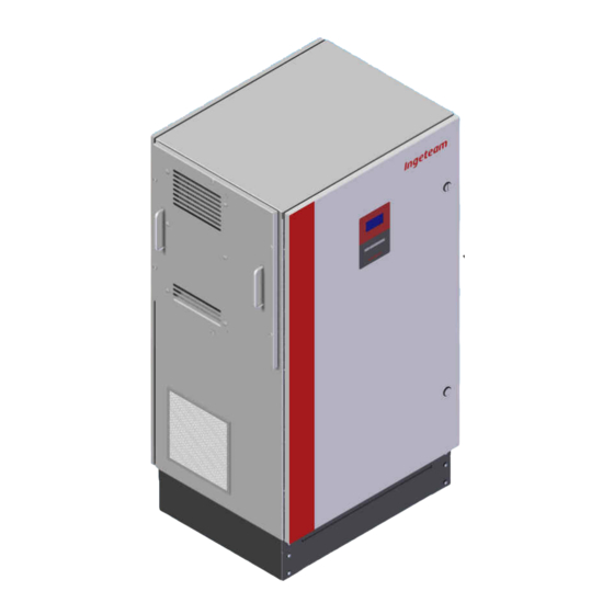
- Page 1 Installation Manual Ingecon® Sun Three-Phase Inverter INGECON SUN SMART Ingecon Sun Three-Phase Inverter – Installation Manual Ref.: AAS2000IKI02 Pg. 1 de 40 Rev.:_ Dec-2009 Ingeteam Energy S.A. 12/2009...
-
Page 2: Table Of Contents
Ingecon® Sun Three-Phase Inverter Ingecon® Sun Three-Phase Inverter – Installation Manual Note: Because of the continuous evolution of its products, Table of Contents Ingeteam Energy S.A. reserves the right to update and modify this manual without prior notice. Page Introduction ...................5 1.1 General Remarks on Safety ................5... - Page 3 Installation Manual Ingecon® Sun Three-Phase Inverter Uninstalling the inverter ...............21 Preventive Maintenance ..............23 6.1 Maintenance Procedures ...................23 Using the display and keyboard ............25 7.1 Keyboard ......................25 7.2 Display .......................26 7.3 Main Menu ......................27 7.4 Monitoring ......................27 7.5 Stop reasons ......................30 7.6 Adjustments .......................31 7.7 Inverter data .......................31 Troubleshooting ...................32...
- Page 4 Installation Manual Ingecon® Sun Three-Phase Inverter documentation related to this manual CATALOGUES Ingecon® Sun Commercial Catalogue PC00ISA03 MANUALS Ingecon® Sun Ingecon® Sun IP20 Ingecon® Sun Single-Phase Three-Phase Inverter Three-Phase IP54 Installation Manual Installation Manual Installation Manual AAS2000IKR03 AAS2000IKR01 AAP2000IKR01 Ingecon® Sun Hybrid Ingecon®...
-
Page 5: Introduction
Installation Manual Ingecon® Sun Three-Phase Inverter Introduction Carefully read this manual and carry out the installation in conformity with the instructions provided. General Remarks on Safety Attenzione. Non aprire. Solo personale autorizzato. Caution. Do not open. Only authorized operators The operations described in this manual must be performed exclusively by duly qualified operators, especially trained to work on electrical installations and having a suitable knowledge of this manual and of the wiring diagrams attached to the switchboard (hereafter the ‘qualified personnel’). - Page 6 To test for absence of voltage it is compulsory to use measuring instruments of Class III - 1,000 Volt. Ingeteam Energy, S.A. cannot be held responsible for any damage arising from any improper use of its products. Ref.: AAS2000IKI02 Pg.
-
Page 7: Description Of The Activities On The Device
Installation Manual Ingecon® Sun Three-Phase Inverter Description of the Activities on the Device INSPECTION: This kind of intervention involves opening the covering to carry out a visual inspection. MANOEUVRE: Any activity related to software loading, testing of the warming/cooling systems and corrective maintenance on the system (except on the switchboards) carried out by means of the operator-machine interface. -
Page 8: Assembly
In case of non-compliance with these provisions, the warranty may become null and void without any responsibility of INGETEAM. The Inverter must be placed VERTICALLY, even in case it is necessary to return it to the factory. -
Page 9: Location
Installation Manual Ingecon® Sun Three-Phase Inverter IIdentifying the equipment The serial number clearly identifies the inverter. All communications with Ingeteam S.A. should indicate this number.. Avda. Ciudad de la Innovación, 13 31621 Sarriguren (Navarra) ESPAÑA solar.energy@ingeteam.com Tel 948 288000 Fax 948 288001... - Page 10 Installation Manual Ingecon® Sun Three-Phase Inverter Facilitate the circulation of incoming air through the vents and through the lower pit, if present, and also the outgoing air through the upper vents. Avoid corrosive enviroments. Due to its considerable weight, the equipment needs to be positioned on a firm and completely horizontal floor.
-
Page 11: Disposal
Installation Manual Ingecon® Sun Three-Phase Inverter Following screwing prescriptions are mandatory: - Minimun distance between the center of thedrill on the concrete slab to its borders of 72 mm. - Diameter of the drill on the concrete slab to its borders of 8 mm. - Minimun depth of thedrill on the concrete slab of 65 mm. -
Page 12: Electrical Connection
Installation Manual Ingecon® Sun Three-Phase Inverter 3. Electrical connection Once the equipment has been mounted in its definitive location, the electrical connections can be made to the auxiliary equipment, the Power Grid and the PV array. The Ingecon Sun inverter electrical connection must be made by qualified person- ®... -
Page 13: Opening The Equipment And Access
Installation Manual Ingecon® Sun Three-Phase Inverter Opening the equipment and access Before opening the front door, make absolutely certain that there are no live voltages inside the cabinet. For this, the equipment needs to be disconnected from the PV array and from the power grid. -
Page 14: Earth Fault Contact / Grid Connection Indicator
The equipment is factory configured to perform one or other function; the function option must be expressly requested when the order is sent to Ingeteam Energy S.A. The normally open contact admits a voltage of 230 Vac and a maximum current of 10 A. -
Page 15: Gsm / Gprs - Modem Communication Connection
Installation Manual Ingecon® Sun Three-Phase Inverter GSM / GPRS - Modem communication connection At the installer’s request, optionally, the inverters may incorporate hardware to enable a GMS / GPRS communication link to be established with the inverter. Consult the communication accessory installation manual «AAX2002IKI01 Communication accessories Installation Manual.»... -
Page 16: Connection To The Power Grid
Installation Manual Ingecon® Sun Three-Phase Inverter Connection to the Power Grid The ports for the Power grid connection cables are located either on the cabinet side or base. If the distance between the inverter and the Grid connection point requires the use of a greater cable section, then the use of an external distribution box, located close to the inverter, is compulsory in order to change from one section to another. -
Page 17: Connection To The Pv Array
Installation Manual Ingecon® Sun Three-Phase Inverter 3.10 Connection to the PV array The cables connecting the equipment to the PV array access the unit through the PG cable glands located on the cabinet sides or base. Prior to any manipulation, always check to ensure there is no electrical hazard at the PV array voltage input. -
Page 18: Prior To Start Up
Installation Manual Ingecon® Sun Three-Phase Inverter 3.11 Prior to start up The INGECON SUN inverters are equipped with a series of MT breakers SMART that protect different parts of the unit. Before the installation can be started up, these breakers need to be closed. Prior to manipulating the MT breakers in any way, first check that there are no electrical hazards in the unit interior. -
Page 19: Start-Up
Installation Manual Ingecon® Sun Three-Phase Inverter 4. Start up The inverter may only be started up once all the connections indicated in the previous section have been made and once the unit has been perfectly sealed. 4.1 Equipment checking The INGECON SUN elements are protected by MT brakers. -
Page 20: Power Up
Installation Manual Ingecon® Sun Three-Phase Inverter 4.2 Power up Once you have made a general visual inspection, checked the cabling and ensured that the unit is sealed correctly, you can then proceed to power up the equipment, whilst maintaining it in the stop position. Follow the guidelines set out in the equipment-specific instruction manual. -
Page 21: Uninstalling The Inverter
Any installation work requiring the unit to be opened must be performed in a dry atmosphere, to prevent the ingress of moisture that could condensate and damage the electronics. Ingeteam Energy S.A. will assume no liability for damages caused by the improper use of its equipment. Ref.: AAS2000IKI02 Pg. - Page 22 The «User Manual» provides the Authorised Manager with information on the location of the components to be decontaminated. INGETEAM ENERGY S.A. don’t accept responsability of hazard produced by a inappropiate use of the devices. Any change in the device have to be previously suggested to INGETEAM.
-
Page 23: Preventive Maintenance
Installation Manual Ingecon® Sun Three-Phase Inverter 6. Preventive Maintenance Recommended Preventive Maintenance Tasks will be done ONCE A YEAR. All Maintenance Procedures should be should only be carried out by suitable qualified personnel. There is a serious electrical discharge hazard. The set of conditions detailed in Chapter1 should be considered to acess to compartment enclosures. - Page 24 Installation Manual Ingecon® Sun Three-Phase Inverter Check the correct ventilation of the equipment: Check the state of the ventilator filters; Proceed to clean and replace it if necessary. Extract the filter removing previously the ventilation grid. Beat softly the filter to separete particles fixed on the filter. Use vacuum cleaner or similar.
-
Page 25: Using The Display And Keyboard
Installation Manual Ingecon® Sun Three-Phase Inverter 7. Using the Screen and Keyboard The Ingecon® Sun inverters are equiped with a «Screen + Keyboard» unit for user and installer - machine communications. This interface displays the principal internal parameters and allows the entire system to be adjusted during installation. -
Page 26: Display
Installation Manual Ingecon® Sun Three-Phase Inverter Display The display consists on: Upper line, where current time and date appear. Internal clock adjust Summer / Winter time authomatically. Central zone, where are shown instantaneous values of PV Array Voltage, Power injected by the inverter, and Output Voltages. -
Page 27: Main Menu
Installation Manual Ingecon® Sun Three-Phase Inverter Main menu Main menu has four submenus: MONITORING. Main parameters and internal variables are shown here. This data inform about the Status of the equipment. STOP REASONS. Five last Stop Reasons are shown here. AJUSTSMENTS: All adjustsments of the inverter are shown here. - Page 28 Installation Manual Ingecon® Sun Three-Phase Inverter Screen 2. Vdc: Voltage provided by the solar panels to the inverter in Volts. Vac1: Inverter output voltage for Power Grid phase 1 in volts. Vac2: Inverter output voltage for Power Grid phase 2 in volts. Vac3: Inverter output voltage for Power Grid phase 3 in volts.
- Page 29 Installation Manual Ingecon® Sun Three-Phase Inverter Alarmas Hist: From the«Alarma Inv» menu, pressing provides access to the submenu «Hist.Alarm», which shows the history of all alarms that have been activated since the inverter was last connected to the grid. TempInt: Inverter Power Electronics Temperature.
-
Page 30: Stop Reasons
Installation Manual Ingecon® Sun Three-Phase Inverter STOP REASONS In this menu you can see the list of the last five reasons for an inverter shutdown, and time and date of each one. 12:00 09/01/09 STOP REASONS 13:43 (08/01) -> MANUAL STOP 17:30 (07/01) ->... -
Page 31: Adjustments
Installation Manual Ingecon® Sun Three-Phase Inverter AJUSTMENTS Date and Date The current time and date can be changed from this menu. The internal clock automatically makes the time change from summer / winter. Change Inverter Number In this menu is assigned the number of the inverter in the installation. It’s neccessary to configure the communications. -
Page 32: Troubleshooting
Installation Manual Ingecon® Sun Three-Phase Inverter Troubleshooting This is a troubleshooting guide to help resolve problems that may arise with regard to the Ingecon Sun SMART installation. ® It isexplained how to replace some components or make some adjustments too. Any probelms arising with the Ingecon Sun SMART should only be resolved by ®... -
Page 33: Orange Led
Probably there are some problems on the grid. When it will disappear, inverter will work again. If problem persists, check the connection to the grid. If problem persists, contact with Ingeteam Energy S.A. 0800H, Failure in power electronic. There are two possible reasons: - There is a ground fault contact in DC circuit. - Page 34 Installation Manual Ingecon® Sun Three-Phase Inverter Procedure to determine which of the two causes is responsible for the insulation failure. Go to the submenu where PV array voltages are shown (PPV and NPV). PPV and NPV values will show us where is the fault. We will disconnect the PV array by PV panel quick connectors to determine if the fault is in or out the inverter.
-
Page 35: List Of The Alarms And Shutdown Reasons
Installation Manual Ingecon® Sun Three-Phase Inverter List of alarms and shutdown reasons The following table shows the reasons that can be in relation with each alarm: ALARM SHUTDOWN REASON DESCRIPCTION 0x0000 No shutdown No alarm, the inverter will start up if it has enough power 0x0001 FREC_ALARM Grid Frequency out of range... -
Page 36: Inverter Alarms Caused By Protections
Installation Manual Ingecon® Sun Three-Phase Inverter Inverter alarms caused by protections 0100H, AC circuit protections. It appears when an AC protection has shotdown. Monitorised elements are: Which are Surge Arresters and contactor Protections. In normal operation, every switch has to be closed except of contactor circuit. If there is and alarm, signal circuit has to be checked to verify where the circuit is opened. -
Page 37: Replacement Of The 'Electronics Block
Installation Manual Ingecon® Sun Three-Phase Inverter Replacement of the «electronics block» The principal electronic cards of the inverter (control card, power card, IGBTs etc) constitue the basic equipment block and are grouped together in a stainless steel cabinet called the «electronics block» In the event of an equipment failure requiring the replacement of the above mentioned «electronics block»... -
Page 38: Replacement Of The Control Board
Installation Manual Ingecon® Sun Three-Phase Inverter Replacement of the Control Board Control Board contains the software of the equipment. If it has to be removed, proceed as follows: Disconnect the equipment from the power grid and PV array. Wait at least 10 minutes for the internal capacitance to discharge. Check that there is no voltage in the equipment. - Page 39 Installation Manual Ingecon® Sun Three-Phase Inverter NOTES Ref.: AAS2000IKI02 Pg. 39 de 40 Rev.:_ Dec-2009...
- Page 40 Avda. Ciudad de la Innovación, 13 31621 Sarriguren (Navarra) Tel +34-948 288 000 Fax +34-948 288 001 http://www.ingeteam.com Ingeteam Energy, S.A. www.ingeteam.com...
Need help?
Do you have a question about the INGECON SUN SMART and is the answer not in the manual?
Questions and answers