Advertisement
Quick Links
Kit de autoconsumo instantáneo para
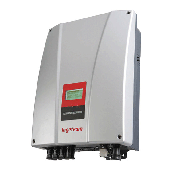
INGECON SUN Lite
Instant self-consumption kit for
INGECON SUN Lite
Ingeteam Power Technology, S.A.
Energy
AAY2002IKH01_A
Avda. Ciudad de la Innovación, 13
Tel.: +34 948 28 80 00
10/2013
31621 SARRIGUREN (Navarra) - Spain
Fax: +34 948 28 80 01
e-mail: solar.energy@ingeteam.com
A
B
C
D
E
E
Castellano
English
A.
Red.
A.
Grid.
B.
Interruptor de Control de Potencia (ICP).
B.
Circuit breaker switch.
C.
Diferencial.
C.
Residual current device.
D.
Vatímetro A65.
D.
Wattmeter A65.
E.
Cargas.
E.
Loads.
F.
INGECON SUN Lite.
F.
INGECON SUN Lite.
G.
Paneles solares.
G.
Solar panels.
W
Castellano
Conexión del vatímetro
Todas las conexiones se deberán realizar sin tensión.
El vatímetro se debe instalar sobre carril DIN. Es importante instalar el vatímetro en el punto de conexión de la vivienda
después del Interruptor de Control de Potencia (ICP) y del diferencial, y antes de que el cableado de la vivienda se
bifurque a todas las cargas y al inversor, tal y como muestra el esquema de la instalación anterior.
Para realizar las conexiones quitar las dos tapas protectoras de las conexiones para tener acceso a las mismas.
Conectarlo como muestra la figura F1, teniendo en cuenta las el esquema eléctrico del sistema visto anteriormente.
Se debe conectar un puente entre los puntos 1 y 4 del vatímetro (ver figura F2).
Con el vatímetro se adjunta un conector aéreo RS-485 (ver figura F3) para conectar el vatímetro al INGECON SUN Lite.
Para cablear correctamente dicho conector seguir las siguientes instrucciones.
Las conexiones con el vatímetro (ver figura F2) se realizarán tal y como se describe a continuación:
Conexión
Señal
Neutro del inversor
11
Neutro de red
Línea de red
1
Puente con 4
4
Puente con 1
7
-
3
Línea del inversor
6
-
9
-
41
Amarillo (A-)**
42
Verde (B+)*
43
Blanco (GND)***
Una vez se ha conectado el vatímetro a la red siguiendo el esquema anterior, conectar éste al INGECON SUN Lite
mediante el cable RS-485 proporcionado (ver figura F4). Las cargas siempre se conectarán entre el vatímetro y el
INGECON SUN Lite (ver esquema de la instalación).
English
Connecting the Wattmeter
All the connections must be made without voltage.
The Wattmeter must be installed on the DIN rail. The Wattmeter should be installed at the connecting point of the home
after the circuit breaker switch and residual current device, and before the wiring of the home is branched off to all the
loads and to the inverter, as shown in the diagram of the previous installation.
To make the connections, get access to the connections by removing the two protective caps.
Connect it as shown in Figure F1 , taking into account the wiring diagram of the system as seen above.
A jumper must be connected between points 1 and 4 of the Wattmeter (see Figure F2 ).
Attach a RS-485 connector (see figure F3 ) to connect the Wattmeter to the INGECON SUN Lite. To correctly cable this
connector, follow the instructions below.
RS-485
Connections with the Wattmeter (see Figure F2 ) should be carried out as described below:
F
Connection
Signal
Inverter neutral
11
Grid neutral
Grid line
1
G
Jumper with 4
4
Jumper with 1
7
-
3
Inverter line
6
-
9
-
41
Yellow (A-) **
42
Green (B+) *
43
White (GND) ***
Once you have connected the Wattmeter to the grid using the diagram above, connect this to the INGECON SUN
Lite using the RS-485 cable provided (see Figure F4 ). Loads should always connect between the Wattmeter and the
INGECON SUN Lite (see installation diagram).
Pin
Señal
1
Verde (B+)*
2
Amarillo (A-)**
3
Blanco (GND)***
4
-
-
* El pin 1 del conector aéreo debe conectarse al punto de
conexión 42 del vatímetro.
** El pin 2 del conector aéreo debe conectarse al punto de
conexión 41 del vatímetro.
*** El pin 3 del conector aéreo debe conectarse al punto de
conexión 43 del vatímetro.
Pin
Signal
1
Green (B+) *
2
Yellow (A-) **
3
White (GND) ***
4
-
-
* Pin 1 of the connector must be connected to connection
point 42 of the Wattmeter.
* Pin 2 of the connector must be connected to connection
point 41 of the Wattmeter.
* Pin 3 of the connector must be connected to connection
point 43 of the Wattmeter.
11
1
3
4
L1
N
F1
11
1
4
7
E
41 42 43
3
6
9
31 32 33
F2
Castellano
A.
Conexiones.
B.
Joystick.
C.
LED.
D.
Selector.
English
A.
Connections.
B.
Joystick.
C.
LED.
D.
Selector.
4
1
3
2
F3
F4
A
B
C
D
A
E.
Display.
E.
Display.
Advertisement

Related Manuals for Ingeteam INGECON SUN Lite


Summary of Contents for Ingeteam INGECON SUN Lite
- Page 1 A jumper must be connected between points 1 and 4 of the Wattmeter (see Figure F2 ). Attach a RS-485 connector (see figure F3 ) to connect the Wattmeter to the INGECON SUN Lite. To correctly cable this connector, follow the instructions below.
- Page 2 After installing and connecting the Wattmeter it is necessary to set up the INGECON SUN Lite inverter for it to This section lists the guidelines to reset the serial configuration only in the event that it loses its configuration.
Need help?
Do you have a question about the INGECON SUN Lite and is the answer not in the manual?
Questions and answers