Table of Contents
Advertisement
Quick Links
Advertisement
Table of Contents

Related Manuals for Insportline Air Beast


Summary of Contents for Insportline Air Beast
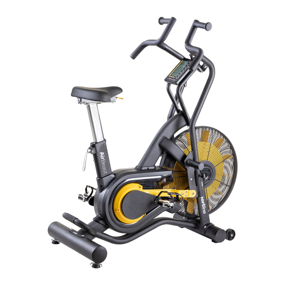
- Page 1 USER MANUAL – EN IN 18714 Air Exercise bike inSPORTline Air Beast...
-
Page 2: Table Of Contents
CONTENTS SAFETY PRECAUTIONS ........................3 DIAGRAM ..............................4 PARTS LIST ............................5 ASSEMBLY ............................. 7 FEATURES............................14 CONSOLE ............................. 16 PROGRAMS ............................18 MAINTENANCE ............................ 21 CORRECT BODY POSTURE ....................... 21 WARM UP EXERCISE .......................... 21 ENVIRONMENT PROTECTION ......................23 TERMS AND CONDITIONS OF WARRANTY, WARRANTY CLAIMS .......... -
Page 3: Safety Precautions
SAFETY PRECAUTIONS • Read all instruction in this manual before using this equipment. • Use the machine only for its intended use as described in this manual. • Inspect and tighten all the loose parts before this equipment is used. •... -
Page 4: Diagram
DIAGRAM... -
Page 5: Parts List
PARTS LIST Name Name Main Frame Front Fan Wheel Cover - L Ribbed Belt Wheel - 360mm Front Fan Wheel Cover - R Ribbed Belt - 690 J7 Main Body Belt Cover (L) Magnetic (15 X 7mm) Main Body Belt Cover (R) Steel - Fan Sensor Housing Phillip Head Self Tapping Screw (M4... - Page 6 Fan Wheel Axle (OD12 X Allen Head Bolt (M8 X 40mm) 155mm) Seat Post Mounting Cap M8 Cap nut Seat Post Reducer Spacer Foot Stop Allen Head Bolt (M6 X 10mm) Phillip Head Machine Screw (M4 x 12mm) Metal Sleeve - (Ø10 X 43.2mm) Rear Stabilizer Rear Stabilizer End Cap - Ø101.6 Cam Handle...
-
Page 7: Assembly
Steel - Fan Wheel Cover - R ASSEMBLY Name Main frame Front stabilizer Rear stabilizer Left handlebar Right handlebar Console holder Holder Console Foot peg Pedal Pedal Fix plate End cap Screw M8x30 mm M8 Nylon nut Disc spring spacer Screw M8x30 mm Allen bolt M10x20 mm Lubricate oil... - Page 9 Attach the front stabilizer • Loosen bolts (J6) from the cardboard tube and remove the cardboard tube. • Attach front stabilizer (B) to the main frame (A) with bolts (J6) and tighten them with 6mm Allen key. • Lubricate the bolts before fastening. Attach the rear stabilizer •...
- Page 10 Attach dual action handlebars Left handlebar • Slide handlebar (D1) to the axle carefully. • Install the foot peg (G) as shown in the picture. • Attach end cap (J1) to the peg (G). • Make sure that the peg (G) is fully tightened with Allen key. Installing of fixing plate and connection bar •...
- Page 11 Right handlebar • Slide handlebar (D2) to the axle carefully. • Install the foot peg (G) as shown in the picture. • Attach end cap (J1) to the peg (G). • Make sure that the peg (G) is fully tightened with Allen key. Installing of fixing plate and connection bar •...
- Page 12 Pedals Left pedal • Loosen the screw (J7) on the left crank arm. • Attach the left pedal (H1) to the left crank arm and fasten with wrench 14/15 • Fasten the screw (J7) anti clock wise to the crank arm with 5 mm Allen key. Right pedal •...
- Page 13 Attach the console holder • Attach the holder (E) to the front of the main frame (A) with two screws (J2) and secure it with 5mm Allen key. • Connect the sensor cable and middle wire together. • Lubricate the screws before fastening. Attach the console •...
-
Page 14: Features
FEATURES Adjusting the seat • Pull the adjustment grip (A55) and adjust the seat. • Push back the grip (A55) after adjusting the seat. Adjusting the seat height • Pull the handle (A32) and adjust the height. • Push down the handle (A32) after adjusting the height. •... - Page 15 Unlock the dual arms • Pull and twist the T knob. • Make sure that the T knob is parallel with the dual arm. • Release the T knob as shown in the picture Lock the dual arms • Pull and twist the T knob to the dual arm with right hand. •...
-
Page 16: Console
CONSOLE Quick start Use this mode if you want quick exercise session and you are not interested in setting up any data. • Pedal for few second to power up the console. • Press START button. • The values of WATTS, SPEED, RPM, HEARH RATE (if detected) will be displayed. •... - Page 17 Display INTERVAL Indicate the current section GO or REST period. 8:88 - show current countdown to GO or REST period. TOTAL TIME 88:88 – count up GO and REST time intervals of the program. 88/88 – shows current interval and total count of intervals in the program.
-
Page 18: Programs
Indicates current heart rate in beats per minute (bpm), which is detected by wireless heart rate chest belt. 65% of – indicates target exercise at 65% of your maximum heart rate. 80% of – indicates target exercise at 80% of your maximum heart rate. - Page 19 INTERVAL 20/30 • Turn on the console. • Press the interval 20/30 to select program. • Default interval number 0/08 is displayed. • Default time segment of REST 0:30 is displayed in the INTERVAL window. • Press ENTER to confirm the setting. •...
- Page 20 Target distance • Turn on the console. • Press the target distance to select program. • buttons to set target distance (0.1 – 999.9 km). Press ENTER to confirm. • Press START to begin the workout and then star pedaling. The program will not start until you begin exercising.
-
Page 21: Maintenance
MAINTENANCE • Always place the product in dry, clean and dustless place. • Use soft, damp cloth for cleaning. • Do not clean electrical components, before cleaning unplug the device. • Safety of the device can be maintained only if the device is checked regularly. This includes any ropes, pulleys, nuts, bolts, moving parts, bushes, chain etc. - Page 22 Inner Thigh Stretch Sit with the soles of your feet together with your knees pointing outward. Pull your feet as close into your groin as possible. Gently push your knees towards the floor. Hold for 15 counts. Hamstring Stretch Sit with your right leg extended. Rest the sole of your left foot against your right inner thigh.
-
Page 23: Environment Protection
ENVIRONMENT PROTECTION After the product lifespan expired or if the possible repairing is uneconomic, dispose it according to the local laws and environmentally friendly in the nearest scrapyard. By proper disposal you will protect the environment and natural sources. Moreover, you can help protect human health. - Page 24 VAT ID: CZ26847264 Phone: +420 556 300 970 E-mail: eshop@insportline.cz reklamace@insportline.cz servis@insportline.cz Web: www.insportline.cz INSPORTLINE s.r.o. Headquarters, Warranty & Service centre: Elektricna 6471, 911 01 Trencin, Slovakia CRN: 36311723 VAT ID: SK2020177082 Phone: +421(0)326 526 701 E-mail: objednavky@insportline.sk reklamacie@insportline.sk servis@insportline.sk...
- Page 25 Web: www.insportline.sk Date of Sale: Stamp and Signature of Seller:...
Need help?
Do you have a question about the Air Beast and is the answer not in the manual?
Questions and answers