Table of Contents
Advertisement
Quick Links
Advertisement
Table of Contents

Subscribe to Our Youtube Channel
Related Manuals for Insportline Basic BT


Summary of Contents for Insportline Basic BT
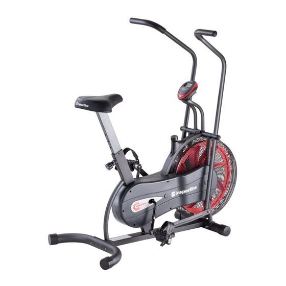
- Page 1 USER MANUAL – EN IN 23514 AirBike inSPORTline Basic BT...
-
Page 2: Table Of Contents
CONTENTS SAFETY INSTRUCTIONS ........................3 ASSEMBLY ............................. 4 CONSOLE ............................. 11 USE ............................... 12 EXERCISING INSTRUCTIONS ......................12 CORRECT BODY POSTURE ....................... 13 MAINTENANCE ............................ 13 STORAGE ............................. 13 IMPORTANT NOTICE ........................... 13 ENVIRONMENT PROTECTION ......................14 DIAGRAM .............................. 15 PARTS LIST ............................ -
Page 3: Safety Instructions
SAFETY INSTRUCTIONS • Read all instruction in this manual before using this equipment and keep it for future references. • Use the machine only for its intended use as described in this manual. • Inspect and tighten all the loose parts before this equipment is used. •... -
Page 4: Assembly
ASSEMBLY Pic. 1 Pic. 2 Pic. 3/4 Pic. 5 Pic. 6L/10R Pic. 7... - Page 5 Pic. 8 Pic. 14 Pic. 15/16 Pic. 17 Pic. 21 Name Qty. Main frame Rear stabilizer Top handlebars (L/R) Seat post 6/10 Lower handlebars and connection rod (L/R) Rear stabilizer Front stabilizer Console 15/16 Pedals (L/R) Seat Axle...
- Page 6 SPOJOVACÍ MATERIÁL Pic. Name Qty. Screw Allen screw Arc washer Arc washer Knob End cap Wrench Allen key...
- Page 7 STEP 1 Attach the front stabilizer (8) to the main frame (1) with 2 screws (11), 2 washers (24) and 2 nuts (19). Attach the rear stabilizer (8) to the main frame (1) with 2 screws (11), 2 washers (24) and 2 nuts (19). STEP 2 Attach the left and right handlebar (3,4) to the lower handlebars (6 L / R).
- Page 8 STEP 3 Remove the washers (26) and the nut (20) on one side of the axis (21). Insert the axis (21) through the hole in the right handlebar (4), main frame (1) and the handlebar (3). Then attach the washers (26) and nuts (20).
- Page 9 STEP 5 Remove the nuts (30 and 22), the metal bushes (28 and 29) from the right and left pedals (15 and 16). Insert the left pedal (15) into the bushing (28), the connection rod (10), the bushing (29) and the left crank (9).
- Page 10 STEP 7 Connect the sensor cables (12 and 18). Attach the console bracket (7) to the main frame (1). Fasten with 2 screws (13). Attach console (14) to console bracket (7) and secure with screws (27). Plug the sensor cable (12) into the back of the console (14).
-
Page 11: Console
CONSOLE The console turns on automatically when a motion signal is received. When you stop the exercise the console will automatically shut down after 4 minutes of inactivity. BUTTONS MODE Press MODE for SCAN– TIME, SPEED, DISTANCE, CALORIES or ODO every 4 seconds Press MODE during SCAN to choose displayed data Set a target for time, distance or calories... -
Page 12: Use
Exercise on the exercise bike is based on very simple movements, but you will surely fall in love with them. Thanks to simplicity of the exercise on the exercise bike in can be done by elderly people. Prior to exercise, it is necessary to adjust the height of the saddle. It is important that you sit comfortably. The bicycle saddle must be set so that you can hold the ergonomically shaped handles when sitting. -
Page 13: Correct Body Posture
Upper thigh Lean against a wall with one hand. Reach down and behind you. Lift up your right or left foot to your buttock as high as possible. Keep for 30 seconds and repeat twice for each leg. Hamstring stretched Sit and outstretch your right leg. -
Page 14: Environment Protection
• Consult your doctor before starting training on the exercise bike. Your doctor should evaluate whether you are physically fit to use the machine and how much effort you are able to undergo. Incorrect exercise or switching of the body can harm your health. •... -
Page 15: Diagram
DIAGRAM... -
Page 16: Parts List
PARTS LIST Name Qty. Name Qty. Main frame Self-tapping screw Rear stabilizer Reinforcing plate Top handlebar L Metal sleeve Top handlebar R Sleeve Seat post Bearing set 6 L/R Handrail bottom bar (L/R) Gasket Console holder Front stabilizer Rear stabilizer end cap Crank Front stabilizer end cap Connection rod... -
Page 17: Terms And Conditions Of Warranty, Warranty Claims
TERMS AND CONDITIONS OF WARRANTY, WARRANTY CLAIMS General Conditions of Warranty and Definition of Terms All Warranty Conditions stated hereunder determine Warranty Coverage and Warranty Claim Procedure. Conditions of Warranty and Warranty Claims are governed by Act No. 89/2012 Coll. Civil Code, and Act No. - Page 18 26847264 VAT ID: CZ26847264 Phone: +420 556 300 970 E-mail: eshop@insportline.cz reklamace@insportline.cz servis@insportline.cz Web: www.inSPORTline.cz inSPORTline s.r.o. Headquaters, warranty & service center: Električná 6471, Trenčín 911 01, SK CRN: 36311723 VAT ID: SK2020177082 Phone: +421(0)326 526 701 E-mail: objednavky@insportline.cz reklamacie@insportline.cz servis@insportline.cz...
Need help?
Do you have a question about the Basic BT and is the answer not in the manual?
Questions and answers