Table of Contents
Advertisement
Quick Links
Advertisement
Table of Contents

Related Manuals for CAB AXON 2


Summary of Contents for CAB AXON 2
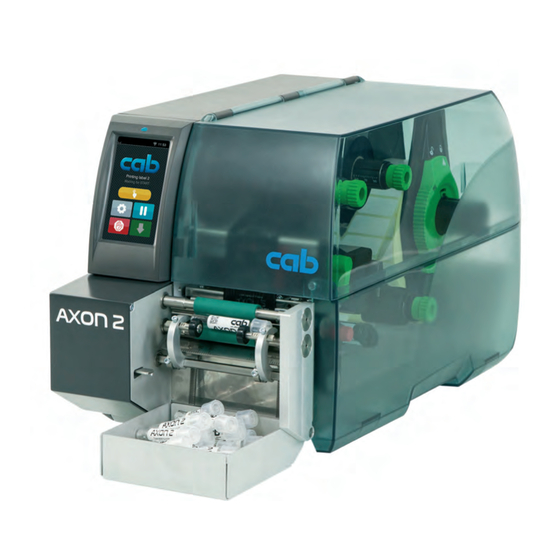
- Page 1 Original Instructions Labelling System AXON 2 MADE IN GERMANY...
- Page 2 Edition: 09/2019 - Part No. 9003455 Copyright This documentation as well as translation hereof are property of cab Produkttechnik GmbH & Co. KG. The replication, conversion, duplication or divulgement of the whole manual or parts of it for other intentions than its original intended purpose demand the previous written authorization by cab.
-
Page 3: Table Of Contents
Table of Contents Introduction ............................4 Instructions ............................... 4 Intended Use ............................4 Safety Instructions ............................ 5 Environment ............................. 5 Installation .............................. 6 Device Overview ............................6 Setting Up ..............................8 Connecting ............................... 9 2.3.1 Connecting to Power Supply ......................9 2.3.2 Connecting to a Computer or Computer Network ................ -
Page 4: Introduction
The device may only be used for its intended purpose and if it is in perfect working order, and it must be used with regard to safety and dangers as stated in that manual. • Usage for the intended purpose also includes complying with that manual. Note! This manual describes a labelling system which is already prepared by cab for the customers application. -
Page 5: Safety Instructions
Introduction Safety Instructions The device version for AC power connection is configured for voltages of 100 to 240 V AC. It only has to be • plugged into a grounded socket. The device version for DC power connection is configured for 24 to 60 V DC. •... -
Page 6: Installation
Installation Device Overview 1 Cover 2 Margin stop 3 Margin stop 4 Roll retainer 5 Ribbon supply hub 6 Ribbon take-up hub 7 Internal rewinder 8 Print unit 9 Tube applicator 10 Tray 11 Touchscreen Display 12 LED "Power on" Figure 1 General overview 13 Ribbon deflection... - Page 7 Installation 24 Release lever 25 Swing arm 26 Pressure roller 27 Transport roller Figure 3 Tube applicator 28 Switch ON/OFF 29 Power connector (devices for 100-240 V AC only) 30 Slot for SD card 31 2 USB host interfaces for keyboard, barcode scanner, Bluetooth adapter or WiFi stick 32 USB Hi-speed device interface...
-
Page 8: Setting Up
Installation Setting Up Note! For adjustments and simple installation work, use the accompanying Allen key located in the top section of the print unit. No other tools are required for the work described here. Note! Please keep the original packaging in case the printer must be returned. Attention! The device and printing materials will be damaged by moisture and wetness. -
Page 9: Connecting
Installation Connecting The standard available interfaces and connectors are shown in Figure 4. 2.3.1 Connecting to Power Supply Figure 6 Connecting to power supply Devices for 100-240 V AC 1. Check that the device is switched off. 2. Plug the power cable into the power connection socket (2). 3. -
Page 10: Touchscreen Display
Touchscreen Display The user can control the operation of the labelling system with the control panel, for example: • Issuing, interrupting, continuing and canceling print jobs, Setting printing parameters, e.g. heat level of the printhead, print speed, interface configuration, language and •... - Page 11 Touchscreen Display In the headline several information are displayed as widgets depending on the configuration: Figure 8 Widgets in the start screen Displays the current data transfer in the form of a falling drop. The Save data stream function is active Configuration manual All received data are stored in a .lbl file.
-
Page 12: Navigation In The Menu
Touchscreen Display Navigation in the Menu Start level Selection level Parameter/function level Figure 9 Menu levels To open the menu select on the start screen. Select a theme in the selection level. Several themes have substructures again with selection levels. To return from the current level to the upper one select . -
Page 13: Loading Material
Loading Material Folding down and up the Applicator Figure 11 Folding down the applicator For loading labels or cleaning the applicator can be folded down from the printer: Folding down Press down the locking lever (1) to unlock the applicator. ... -
Page 14: Loading Media
Loading Material Loading Media 4.2.1 Positioning the Media Roll on the Roll Retainer Figure 12 Loading media 1. Open cover. 2. Fold down the applicator (5) 3. Turn the ring (2) at the margin stop (1) counterclockwise, so that the arrow points to the symbol , and thus release the margin stop. -
Page 15: Inserting The Media Into The Printhead And Fixing The Liner At The Rewinder
Loading Material 4.2.2 Inserting the Media into the Printhead and Fixing the Liner at the Rewinder Inserting the media into the printhead and fixing the liner at the rewinder Figure 13 1. Turn the lever (5) counterclockwise to lift the printhead (3). 2. -
Page 16: Loading Transfer Ribbon
Loading Material Loading Transfer Ribbon Note! With direct thermal printing, do not load a transfer ribbon; if one has already been loaded, remove it. Figure 14 Loading transfer ribbon 1. Clean the printhead before loading the transfer ribbon ( 7.3 on page 21). 2. -
Page 17: Setting The Feed Path Of The Transfer Ribbon
Loading Material Setting the Feed Path of the Transfer Ribbon Transfer ribbon wrinkling can lead to print image errors. The transfer ribbon deflection (3) can be adjusted so as to prevent wrinkles. Figure 16 Setting the feed path of the transfer ribbon Note! The adjustment is best carried out during printing. -
Page 18: Operation
Operation Attention! Printhead damage caused by improper handling! Do not touch the underside of the printhead with the fingers or sharp objects. Ensure that the labels are clean. Ensure that the label surfaces are smooth. Rough labels act like emery paper and reduce the service life of the printhead. Print with the lowest possible printhead temperature. The labelling system is ready for operation when all connections have been made and labels and the transfer ribbon have been loaded. -
Page 19: Standard Operation
Operation Standard Operation Warning! Risk of injury by rotating parts! During operation, rotating parts are freely accessible. Ensure that people‘s clothing, hair, jewelry etc. do not come into contact with the exposed rotating parts. Attention! Peel-off mode must be activated in the software. This is done with the "P command"... -
Page 20: Configuration
Configuration Note! In that chapter are described the specific applicator parameters of the menu Labelling only. For more information about the configuration Configuration Manual of the printer. Start menu. Select Setup > Labelling. Parameter Meaning Default Peel-off position 0.0 mm Shift the position of the dispensed label relative to the dispensing edge. The setting can also be adjusted by the software. The settings of configuration and software are added together. -
Page 21: Cleaning
Cleaning Cleaning Information Danger! Risk of death via electric shock! Disconnect the labelling system from the power supply before performing any maintenance work. The labelling system requires very little maintenance. It is important to clean the thermal printhead regularly. This guarantees a consistently good printed image and plays a major part in preventing premature wear of the printhead. -
Page 22: Fault Correction
Fault Correction Error Display The appearance of an error will be shown on the display: Figure 18 Error display The error treatment is pending on the error type 8.2 on page 22. The display offers the following possibilities to continue after an error occurred: Repeat The print job will be continued after clearing the error cause. - Page 23 Fault Correction Error message Cause Remedy No label size The size of the label is not defined in the Check programming. programming. No tube detected No tube in the labelling area Insert tube. Out of paper Out of label roll Load labels.
-
Page 24: Problem Solution
Fault Correction Problem Solution Problem Cause Remedy Transfer ribbon deflection not adjusted Adjust the transfer ribbon deflection. Transfer ribbon creases 4.4 on page 17 Transfer ribbon too wide Use a transfer ribbon slightly wider than the width of label. Print image has smears or Printhead is dirty Clean the printhead... -
Page 25: Technical Data
Swiss 721 Bold Configuration in Intranet and Internet to be stored TrueType fonts Network Manager (in preparation) For comprehensive technical data see SQUIX 4, www.cab.de/en/squix cab uses free and Open Source Software in its products. www.cab.de/opensource For information see... -
Page 26: Licenses
EC directives. In the event of unauthorized modification of the device or its intended purpose, this declaration will no longer be valid. Device: Labelling System Type: AXON 2 (100 -240 V AC) Applied EU Directives Applied Standards Directive 2006/42/EC on machinery •... -
Page 27: Fcc
EC directives. In the event of unauthorized modification of the device or its intended purpose, this declaration will no longer be valid. Device: Labelling System Type: AXON 2 (24 - 60 V DC) Applied EU Directives Applied Standards Directive 2006/42/EC on machinery •... -
Page 28: Index
Index Applicator folding down and up ....13 Cleaning printhead ........21 print roller ........21 Cleaning information......21 Connecting .........9 Contents of delivery ......8 Device overview .........6 Environment ........5 Errors correction ........22 messages ........22 EU Declaration of Conformity ...26 Important information......4 Intended use ........4 Lithium battery ........5 Loading media ........14 Loading transfer ribbon.....16...
Need help?
Do you have a question about the AXON 2 and is the answer not in the manual?
Questions and answers