Sign In
Upload
Download
Table of Contents
Contents
Add to my manuals
Delete from my manuals
Share
URL of this page:
HTML Link:
Bookmark this page
Add
Manual will be automatically added to "My Manuals"
Print this page
×
Bookmark added
×
Added to my manuals
Manuals
Brands
CAB Manuals
Label Maker
A4+M
Operator's manual
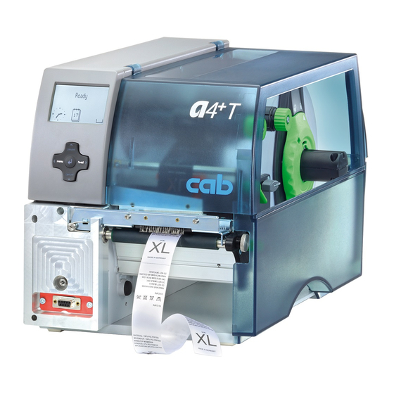
CAB A4+M Operator's Manual
Label printer
Hide thumbs
Also See for A4+M
:
User configuration manual
(56 pages)
1
2
Table Of Contents
3
4
5
6
7
8
9
10
11
12
13
14
15
16
17
18
19
20
21
22
23
24
25
26
27
28
page
of
28
Go
/
28
Contents
Table of Contents
Bookmarks
Table of Contents
Table of Contents
1 Introduction
Instructions
Intended Use
Safety Instructions
Environment
2 Installation
Device Overview
Unpacking and Setting-Up the Printer
Connecting the Device
Connecting to the Power Supply
Connecting to a Computer or Computer Network
Switching on the Device
3 Control Panel
Structure of the Control Panel
Symbol Displays
Printer States
Key Functions
4 Loading Material
Loading Labels or Continuous Media from Roll
Positioning the Media Roll on the Roll Retainer
Inserting a Media Strip into the Printhead
Setting the Label Sensor
Loading Fanfold Labels
Loading Transfer Ribbon
Setting the Feed Path of the Transfer Ribbon
Setting the Head Locking System
5 Printing Operation
Printhead Protection
Synchronization in Cut Mode
Suppressing Backfeed (A4+T Only)
Avoiding Loss of Material (A4+T Only)
6 Cleaning
Cleaning Information
Cleaning the Print Roller
Cleaning the Printhead
7 Fault Correction
Types of Errors
Problem Solution
Error Messages and Fault Correction
8 Media
Media Dimensions
Device Dimensions
Reflex Mark Dimensions
Cut-Out Mark Dimensions
9 Licences
EC Declaration of Conformity
Fcc
10 Index
Advertisement
Quick Links
1
Loading Labels or Continuous Media from Roll
2
Setting the Label Sensor
3
Types of Errors
4
Fault Correction
Download this manual
Operator's Manual
Label Printer
A4 + M / A4 + T
Table of
Contents
Previous
Page
Next
Page
1
2
3
4
5
Advertisement
Table of Contents
Need help?
Do you have a question about the A4+M and is the answer not in the manual?
Ask a question
Questions and answers
Related Manuals for CAB A4+M
Label Maker CAB A2+ User Configuration Manual
(56 pages)
Label Maker CAB a2+ Configuration Instructions
Barcode/label printer (68 pages)
Label Maker CAB A+ Operator's Manual
A+ series label printer (36 pages)
Label Maker CAB A4+T Operator's Manual
Label printer (28 pages)
Label Maker CAB A Series Service Manual
(34 pages)
Label Maker CAB A+ Series Programming Manual
(484 pages)
Label Maker CAB AXON 2 Original Instructions Manual
(28 pages)
Label Maker CAB AXON 2 Assembly Instructions Manual
Tube applicator (18 pages)
Label Maker CAB AXON 1 Original Instructions Manual
(26 pages)
Label Maker CAB EOS1 Configuration Manual
Eos series label printer (42 pages)
Label Maker CAB SQUIX Configuration Manual
(64 pages)
Label Maker CAB SQUIX Operator's Manual
(36 pages)
Label Maker CAB XC Series Operator's Manual
Xc series label printer (30 pages)
Label Maker CAB Hermes+ Operator's Manual
(32 pages)
Label Maker Cab EOS2 Operator's Manual
(28 pages)
Label Maker CAB XD4M Operator's Manual
(30 pages)
This manual is also suitable for:
A4+t
Table of Contents
Save PDF
Print
Rename the bookmark
Delete bookmark?
Delete from my manuals?
Login
Sign In
OR
Sign in with Facebook
Sign in with Google
Upload manual
Upload from disk
Upload from URL


Need help?
Do you have a question about the A4+M and is the answer not in the manual?
Questions and answers