Table of Contents
Advertisement
Quick Links
Advertisement
Table of Contents

Subscribe to Our Youtube Channel
Related Manuals for CAB AXON 1


Summary of Contents for CAB AXON 1
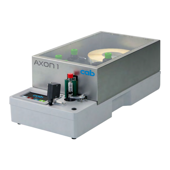
- Page 1 Original Instructions Labelling System AXON 1 MADE IN GERMANY...
- Page 2 Edition: 12/2021 - Part No. 9003675 Copyright This documentation as well as translation hereof are property of cab Produkttechnik GmbH & Co. KG. The replication, conversion, duplication or divulgement of the whole manual or parts of it for other intentions than its original intended purpose demand the previous written authorization by cab.
-
Page 3: Table Of Contents
Table of Contents Introduction ............................4 Instructions ............................... 4 Intended Use ............................4 Safety Instructions ............................ 5 Environment ............................. 5 Installation .............................. 6 Device Overview ............................6 Unpacking and Setting-up ........................7 Connecting the Device ..........................7 2.3.1 Connecting to the Power Supply ......................7 2.3.2 Connecting to a Computer or Computer Network ................ -
Page 4: Introduction
Introduction Instructions Important information and instructions in this documentation are designated as follows: Danger! Draws attention to an exceptionally great, imminent danger to your health or life due to hazardous voltages. Danger! Draws attention to a danger with high risk which, if not avoided, may result in death or serious injury. Warning! Draws attention to a danger with medium risk which, if not avoided, may result in death or serious injury. -
Page 5: Safety Instructions
Introduction Safety Instructions The device is configured for voltages of 100 to 240 V AC. It only has to be plugged into a grounded socket. • • Only connect the device to other devices which have a protective low voltage. Switch off all affected devices (computer, printer, accessories) before connecting or disconnecting. -
Page 6: Installation
Installation Device Overview AXON 1.1 AXON 1.2 1 Touchscreen display 5 Cover (Option) 2 Ribbon take-up hub 6 Internal rewinder 3 Ribbon supply hub 7 Print unit 4 Roll retainer Figure 1 Overview 11 12 13 14 11 12 13 14 AXON 1.1... -
Page 7: Unpacking And Setting-Up
Ensure that all computers and cables connected to the device are grounded. Connect the device to a computer or network by a suitable cable. For details of the configuration of the individual interfaces Configuration Manual cab printers Switching on the Device When all connections have been made: ... -
Page 8: Touchscreen Display
• Issuing, interrupting, continuing and canceling print jobs, Setting printing parameters, e.g. heat level of the printhead, print speed, interface configuration, language and • Configuration Manual cab time of day printers, Configuration Manual cab Control stand-alone operation with a memory module ... - Page 9 Widgets in the start screen Displays the current data transfer in the form of a falling drop. The Save data stream function is active Configuration Manual cab printers All received data are stored in a .lbl file. Configuration Manual cab printers Warning ribbon end ...
-
Page 10: Navigation In The Menu
Touchscreen Display Navigation in the Menu Start level Selection level Parameter/function level Figure 6 Menu levels To open the menu select on the start screen. Select a theme in the selection level. Several themes have substructures again with selection levels. To return from the current level to the upper one select . -
Page 11: Loading Material
Loading Material Note! For adjustments and simple installation work, use the accompanying Allen key located in the top section of the print unit. No other tools are required for the work described here. Loading Labels Figure 8 Loading media Figure 9 Label feed path 1. -
Page 12: Loading Transfer Ribbon
Loading Material Loading Transfer Ribbon Figure 10 Loading transfer ribbon 1. Clean printhead before loading the transfer ribbon ( 7.3 on page 19). 2. Turn lever (1) counterclockwise to lift the printhead. 3. Slide transfer ribbon roll (3) onto the ribbon supply hub (4) 4. -
Page 13: Setting The Feed Path Of The Transfer Ribbon
Loading Material Setting the Feed Path of the Transfer Ribbon Transfer ribbon wrinkling can lead to print image errors. The transfer ribbon deflection (3) can be adjusted so as to prevent wrinkles. Figure 12 Setting the feed path of the transfer ribbon Note! The adjustment is best carried out during printing. -
Page 14: Setting-Up The Applicator
The supporting plate (2) can be set vertically to adjust the position of the label on the tube and therefore to adjust the measure E. P=37 P=10 AXON 1.1 AXON 1.2 Tube length The following correlation can be deduced from the... -
Page 15: Adjusting The Transport Rollers
Setting-up the Applicator Adjusting the Transport Rollers Figure 15 Adjusting the transport rollers The transport rollers (3) can be shifted on the axles (1). Loosen the screws (3). Set the transport rollers in such a way that • the tubes to be labeled are guided over the longest possible length and •... -
Page 16: Menu Settings
Setting-up the Applicator Menu Settings Note! In that chapter are described the specific applicator parameters of the menu Labelling only. For more information about the configuration Configuration Manual cab printers. Start menu. Select Setup > Labelling. Parameter... -
Page 17: Operation
Operation Attention! Printhead damage caused by improper handling! Do not touch the underside of the printhead with the fingers or sharp objects. Ensure that the labels are clean. Ensure that the label surfaces are smooth. Rough labels act like emery paper and reduce the service life of the printhead. -
Page 18: Standard Operation
Attention! Peel-off mode must be activated in the software. This is done with the "P command" in the direct programming. Programming Manual cab printers Note! The labelling process can be modified by setting the following parameters page 16: •... -
Page 19: Cleaning
Cleaning Cleaning Information Danger! Risk of death via electric shock! Disconnect the labelling system from the power supply before performing any maintenance work. The labelling system requires very little maintenance. It is important to clean the thermal printhead regularly. This guarantees a consistently good printed image and plays a major part in preventing premature wear of the printhead. -
Page 20: Fault Correction
Fault Correction Error Display The appearance of an error will be shown on the display: Figure 17 Error display The error treatment is pending on the error type 8.2 on page 20. The display offers the following possibilities to continue after an error occurred: Repeat The print job will be continued after clearing the error cause. - Page 21 Fault Correction Error message Cause Remedy Out of paper Out of label roll Load labels. Error in the paper feed Check paper feed. Out of ribbon Out of transfer ribbon Insert new transfer ribbon. Transfer ribbon melted during printing Cancel current print job. Change the heat level via software.
-
Page 22: Problem Solution
Device is used with the backfeed > smart in Set the backfeed > always in the setup. Horizontal white lines in the the cut or peel-off mode Configuration Manual cab printers print image Print image is irregular, one Printhead is dirty Clean the printhead ... -
Page 23: Technical Data
Technical Data typical possible standard option Tube labeling system Type AXON 1.1 AXON 1.2 Print head Thermal transfer Print method Direct thermal – – ... - Page 24 Network Manager (in preparation) EBCDIC 500 *available for AXON 1 from September 2021 ISO 8859-1 to -10 and -13 to -16 WinOEM 720 Free and Open Source software are part of cab products. UTF-8 For information see www.cab.de/opensource MacRoman DEC MCS...
-
Page 25: Licenses
Marcel Michalski cab Produkttechnik Sömmerda GmbH Am Unterwege 18 - 20 D-99610 Sömmerda Signed for, and on behalf of the Manufacturer Karlsruhe, 24.02.2021 cab Produkttechnik GmbH & Co KG Wilhelm-Schickard-Str. 14 Klaus Bardutzky D-76131 Karlsruhe Managing Director 10.2 NOTE : This equipment has been tested and found to comply with the limits for a Class A digital device, pursuant to Part 15 of the FCC Rules. -
Page 26: Index
Index Adjusting the Pressure Roller ...15 Voltage..........5 Adjusting the Supporting Plate ..14 Adjusting the Transport Rollers ..15 Warning stickers .........5 Cleaning printhead ........19 print roller ........19 Cleaning information......19 Connecting .........7 Contents of delivery ......7 Cut mode ..........17 Environment ........5 Errors correction ........20 messages ........20 types ...........20...
Need help?
Do you have a question about the AXON 1 and is the answer not in the manual?
Questions and answers