Table of Contents
Advertisement
Advertisement
Table of Contents

Related Manuals for CAB hermes+


Summary of Contents for CAB hermes+
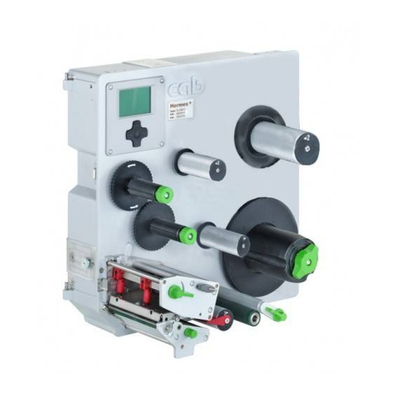
- Page 1 Service Manual Hermes+ Label Printer Made in Germany...
- Page 2 The replication, conversion, duplication or divulgement of the whole manual or parts of it for other intentions than its original intended purpose - in particular the procurement of spare parts for products sold by cab - demand the previous written authori- zation by cab.
-
Page 3: Table Of Contents
Table of Contents Important Information ..........................4 Notes ................................ 4 General Safety Instructions ........................4 Protective Devices ........................... 5 Handling Electricity ..........................5 Procedure in Case of Accidents ......................5 Environment ............................. 5 Tools ................................ 6 Maintenance ............................7 Cleaning by the Operator ......................... 7 Cleaning the Label Sensor ........................ -
Page 4: Important Information
Important Information Notes Important information and instructions are designated as follows: Danger! Draws attention to an exceptionally great, imminent danger to your health or life due to hazardous voltages. Danger! Draws attention to a danger with high risk which, if not avoided, may result in death or serious injury. Warning! Draws attention to a danger with medium risk which, if not avoided, may result in death or serious injury. -
Page 5: Protective Devices
Important Information Protective Devices Warning! There is a risk of injury if protective devices are missing or defective. Replace all protective devices (covers, safety notices, grounding cables etc) after maintenance work has been completed. Replace parts that have become defective or unusable. Wear protective goggles for: •... -
Page 6: Tools
Test collar for transfer ribbon winder (cab Part-No. 5534199) • Distance caliber 0,1 mm (cab Part-No. 5961064) • Gauge for brake adjustment at the label unwinder (cab Part-No. 5961092) Standard tools: • Screw driver Torx, size TX 10, TX 20 •... -
Page 7: Maintenance
Maintenance Cleaning by the Operator The following cleaning work is described in the “Operator's Manual“: • Cleaning the device • Cleaning the printhead • Cleaning the print roller Cleaning the Label Sensor Figure 1 Cleaning the label sensor Danger! Risk of death via electric shock! ... -
Page 8: Replacing Assembly Units
Replacing Assembly Units Replacing the Printhead 4.1.1 Replacing Printhead Hermes+ 2, Hermes+ 4 and Hermes+ 4.3 The printhead can be replaced without the need for fine adjustment. The printhead must be replaced if worn or when switching to a printhead with higher or lower resolution. For better differentiation, the printheads have a label stating the resolution. -
Page 9: Replacing Printhead Hermes+ 6
Replacing Assembly Units Removing the printhead 1. Turn lever (11) counterclockwise to lift the printhead. 2. Remove labels and transfer ribbon from the printer. 3. Lightly keep printhead mounting bracket (8) on the print roller with one finger and screw out screw (7) with the Allen key (12). - Page 10 Replacing Assembly Units Figure 5 Dismounting printhead Hermes+ 6 Dismounting printhead 1. Open the printhead assembly. 2. Remove the labels and transfer ribbon. 3. Press the prithead bracket (7) on the print roller and loosen screw (6) with the hexagon wrench (8). 4.
-
Page 11: Replacing The Print Roller And Transport Roller
Replacing Assembly Units Replacing the Print Roller and Transport Roller Figure 7 Replacing print roller and transport roller Replacing the print roller 1. Turn lever (4) counterclockwise to lift the printhead assembly. 2. Loosen screw (6). 3. Remove ball bearing (5) and print roller (2) through the plate (3). 4. -
Page 12: Replacing The Slipping Clutches
Replacing Assembly Units Replacing the Slipping Clutches The rewinder for the transfer ribbon and the internal rewinder are coupled to a slipping clutch in the main drive. The supply hub of the transfer ribbon is braked with a slipping clutch during printing. Change the slipping clutch when it can no longer be set ... - Page 13 Replacing Assembly Units Removing the brake at the ribbon unwinder 1 Pin 2 Spring 3 Winder axle 4 Tappet 5 Lever 6 Brake 7 Snap ring Figure 10 Brake at the ribbon unwinder 1. Unplug the printer from the electrical outlet. 2.
-
Page 14: Replacing The Brake Shoe At The Label Unwinder
Replacing Assembly Units Replacing the Brake Shoe at the Label Unwinder 9/4x Figure 11 Brake at the label unwinder 1. Turn the knurled knob (8) counterclockwise and remove the margin stop (10) from the unwinder. 2. Loosen 4 screws (9) remove the wall spacer (7). 3. -
Page 15: Replacing The Label Sensor
Replacing Assembly Units Replacing the Label Sensor Notice! Soiling of the label sensor can also cause malfunctions. Before replacing the label sensor, check whether it is soiled and clean it if necessary. 3.1 on page 7. Figure 12 Replacing the label sensor Danger! Risk of death via electric shock! ... -
Page 16: Replacing The Pcb Cpu
Replacing Assembly Units Replacing the PCB CPU Danger! Risk of death via electric shock! Before opening the housing cover, disconnect the device from the mains supply and wait at least one minute until the power supply unit has discharged. 1. -
Page 17: Replacing The Power Supply Unit
Replacing Assembly Units Replacing the Power Supply Unit Danger! Risk of death via electric shock! Before opening the housing cover, disconnect the device from the mains supply and wait at least one minute until the power supply unit has discharged. 1. -
Page 18: Adjustments
Adjustments Measuring and Adjusting the Winding Torques The rewinder for the transfer ribbon and the internal rewinder are coupled to a slipping clutch in the main drive. The supply hub of the transfer ribbon is braked with a slipping clutch during printing. The correct setting of the torques of these slipping clutches is necessary for: •... - Page 19 Adjustments Figure 16 Measuring the winding torque at the transfer ribbon take up hub (left) and supply hub (right) Danger! Risk of death via electric shock! Before opening the housing cover, disconnect the device from the mains supply and wait at least one minute until the power supply unit has discharged.
- Page 20 Adjustments Internal Rewinder Measurement of the winding torque at the internal rewinder occurs by determining the pulling forces with a cord wrapped around the rewinder. The physical relation between the torque and the pulling force is: F= M / r Pulling force [N], Winding torque [Ncm], Radius of the rewinder (38 mm)
-
Page 21: Adjusting The Winding Torques
Adjustments 5.1.2 Adjusting the Winding Torques The winding torque of a winder can be changed at the knurled ring of the respective slipping clutch. The numbers on the knurled ring stand for the value of the winding torque: • 1: Lowest winding torque •... -
Page 22: Adjusting The Brake At The Label Unwinder
Adjustments Adjusting the Brake at the Label Unwinder The brake (9) at the label unwinder is switched on and off by the movement of the swing arm (2). The correct adjustment of the switching point guarantees an accurate label transport and a high positioning accuracy of the peeled labels. -
Page 23: Adjusting The Label Run
Adjustments Adjusting the Label Run Over an eccentric on the 3. deflection roller (5) it's possible to change the angle between roller and chassis and so the direction of the material (2) run. The label material (2) must so run that the material edge touched softly the paper run edge (1) of the chassis. -
Page 24: Adjusting The Printing Mechanism
Adjustments Adjusting the Printing Mechanism Major adjustment of the printing mechanism beyond format-based settings is only required if the printhead assembly has been removed or parts in this area have been replaced. Excluded from this is the replacement of the printhead, after which readjustment is generally not required. -
Page 25: Adjusting The Printhead Position
Adjustments 5.4.2 Adjusting the Printhead Position In order to achieve the best possible print image the following printhead settings are necessary: • Align the heating line with the highest point of the print roller. Density of the print image is the greatest at this point. -
Page 26: Adjusting The Printhead Pressure
Adjustments 5.4.3 Adjusting the Printhead Pressure The printhead pressure can be changed with the screws (1a) and (1b) at the inside and outside of the printhead. Increasing the head contact pressure leads to an improvement of the print image density on the corresponding side and to a shifting of the ribbon feed path in the corresponding direction. -
Page 27: Adjusting The Transfer Ribbon Feed Path
Reset the Heat level to 0 in the printer configuration Configuration Manual. Recheck the setting with the test function Test grid ( Configuration Manual) or a similar print pattern. When using standard cab media, the test printout must show lines with sharp contours and black areas without any parts missing. -
Page 28: Adjusting The Belt Tension
Adjustments Adjusting the Belt Tension 5.5.1 Adjusting the Tension at the Main Drive Motor Belt Danger! Risk of death via electric shock! Before opening the housing cover, disconnect the device from the mains supply and wait at least one minute until the power supply unit has discharged. -
Page 29: Adjusting The Tension At The Rewinder And Transport Roller Belt
Adjustments 5.5.2 Adjusting the Tension at the Rewinder and Transport Roller Belt Danger! Risk of death via electric shock! Before opening the housing cover, disconnect the device from the mains supply and wait at least one minute until the power supply unit has discharged. Figure 29 Adjusting the tension at the rewinder and transport roller belt 1. -
Page 30: Adjusting The Magnetic Clutch
Adjustments Adjusting the Magnetic Clutch A misaligned magnetic clutch can cause a very high and not adjustable torque at the ribbon supply hub. The distance between chassis of the magnetic clutch (2) and the armature disk (3) must be 0.1 mm . Danger! Risk of death via electric shock! ... -
Page 31: Adjusting The Ribbon Saver
Adjustments Adjusting the Ribbon Saver The ribbon saver reduces the consumption of transfer ribbon amongst others by lifting the printhead while feeding blank label areas. The printhead will be lifted by eccentrics (6) which are controlled by a clock wheel (2) and an optical sensor (1). -
Page 32: Troubleshooting And Error Treatment
Troubleshooting and Error Treatment Failure of Device Functions Functional error Possible remedy Medium is not transported Check electrical connections between PCB CPU and motor Check drive mechanism Replace the PCB CPU Replace the motor No print image with medium Check plug connections at the printhead transport Examine printhead cable for damage and replace if necessary Replace the printhead... -
Page 33: Hardware Faults
Troubleshooting and Error Treatment Hardware Faults Error message Cause Fault recovery ADC malfunction Fault on the PCB CPU Replace the PCB CPU FPGA malfunction Fault on the PCB CPU Replace the PCB CPU Invalid setup Fault on the PCB CPU Replace the PCB CPU Voltage error Voltage of the battery on the... -
Page 34: Block Diagram
Block Diagram Figure 34 Block diagram Hermes+... -
Page 35: Layout Diagram Cpu
Layout Diagram CPU Figure 35 Layout diagram PCB CPU - components side... - Page 36 Layout Diagram CPU Figure 36 Layout diagram PCB CPU - soldering side...
-
Page 37: Index
Index Accidents ..........5 Safety instructions ......4 Sensor ribbon saver ......31 Slipping clutches Belt tension .........28, 29 Adjustment ........21 Block Diagram ........34 Replacement .......12 Brake ..........13 Brake label unwinder Test collar .........18 Adjustment ........22 Torque..........18 Replacement .......14 Transfer ribbon feed path ....27 Transport roller .........
Need help?
Do you have a question about the hermes+ and is the answer not in the manual?
Questions and answers