Table of Contents
Advertisement
Quick Links
Advertisement
Table of Contents

Subscribe to Our Youtube Channel
Related Manuals for CAB HERMES Q2L


Summary of Contents for CAB HERMES Q2L
- Page 1 Assembly Instructions Label Printer HERMES Q MADE IN GERMANY...
- Page 2 Edition: 10/2019 – Part No. 9003408 Copyright This documentation, as well as translations thereof, are the property of cab Produkttechnik GmbH & Co. KG. The replication, conversion, duplication or distribution of the whole manual or parts thereof for purposes other than its original intended purpose require previous written authorization by cab.
-
Page 3: Table Of Contents
Table of Contents Introduction ............................4 Instructions ............................... 4 Intended Use ............................4 Safety Instructions ............................ 5 Safety Marking ............................6 Environment ............................. 6 Installation .............................. 7 Device Overview ............................7 Unpacking and Setting-up the Printer ....................10 Connecting the Device ..........................11 2.3.1 Connecting to the Power Supply ......................11 2.3.2... -
Page 4: Introduction
The printer is designed for the integration into a production line. It is intended exclusively for printing suitable materials that have been approved by the manufacturer and for coupling a cab or non-cab applicator which transfers labels from the printer to a product. Any other use or use going beyond this shall be regarded as improper use. -
Page 5: Safety Instructions
Introduction Safety Instructions The device is configured for voltages of 100 to 240 V AC. It only has to be plugged into a grounded socket. • • Only connect the device to other devices which have a protective low voltage. • Switch off all affected devices (computer, printer, accessories) before connecting or disconnecting. •... -
Page 6: Safety Marking
Introduction Safety Marking Figure 1 Safety marking Danger spot ! • Risk of burning on the hot printhead assembly (1). Do not touch the printhead during operation, and allow to cool down before changing material and before disassembly. • Entanglement hazard by turning roller (2). -
Page 7: Installation
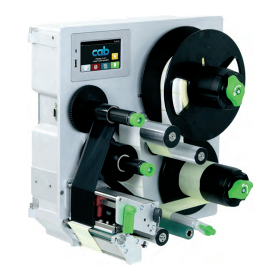
Installation Device Overview 1 Cover (Option) 2 Hinges for cab-applicators 3 Control panel 4 Interface for cab-applicators 5 Ribbon take-up hub 6 Ribbon supply hub 7 Print mechanism 8 Roll retainer 9 Pivot arm with guide roller 10 Internal rewinder... - Page 8 Installation 13 Head locking system 14 Printhead retainer 15 Printhead 16 Peel-off edge 17 Print roller 18 Label sensor 19 Allen key 20 Printhead locking lever Figure 4 Print mechanism 21 Touchscreen display 22 LED Power ON 23 USB host interface for USB memory stick or service key Figure 5 Control panel...
- Page 9 Installation 24 Power switch 25 Power connection jack 26 Slot for SD card 27 2 USB host interfaces for service key, USB memory stick, keyboard, barcode scanner, Bluetooth adapter, WiFi adapter, external control panel or warning light 28 USB Hi-speed device interface 29 Ethernet 10/100 Base-T 30 Serial RS-232 C interface 31 I/O interface...
-
Page 10: Unpacking And Setting-Up The Printer
Installation Unpacking and Setting-up the Printer Lift the printer out of the box. Check printer for damage which may have occurred during transport. Remove foam transportation safeguards near the printhead. Check delivery for completeness. Contents of delivery: •... -
Page 11: Connecting The Device
Installation Connecting the Device 2.3.1 Connecting to the Power Supply The printer is equipped with a wide area power unit. The device can be operated with a supply voltage of 230 V~/50 Hz or 115 V~/60 Hz without adjustment. 1. Check that the device is switched off. 2. -
Page 12: Touchscreen Display
Touchscreen Display The user can control the operation of the printer with the control panel, for example: • Issuing, interrupting, continuing and canceling print jobs, • Starting labelling cycles when operating the printer with applicator, Setting printing parameters, e.g. heat level of the printhead, print speed, interface configuration, language and • time of day ( Configuration Manual), •... - Page 13 Touchscreen Display In the headline several information are displayed as widgets depending on the configuration: Figure 8 Widgets in the start screen Displays the current data transfer in the form of a falling drop. The Save data stream function is active Configuration manual All received data are stored in a .lbl file. Warning ribbon end Configuration manual The remaining diameter of the ribbon supply roll undershoots the set value. SD card installed USB memory installed gray: Bluetooth adapter installed, white: Bluetooth connection active...
-
Page 14: Navigation In The Menu
Touchscreen Display Navigation in the Menu Start level Selection level Parameter/function level Figure 9 Menu levels To open the menu select on the start screen. Select a theme in the selection level. Several themes have substructures again with selection levels. To return from the current level to the upper one select . -
Page 15: Loading Material
Loading Material Note! For adjustments and simple installation work, use the accompanying Allen key located in the upper section of the print unit. No other tools are required for the work described here. Loading Labels 4.1.1 Positioning the Media Roll on the Roll Retainer Figure 11 Loading label roll 1. -
Page 16: Inserting The Labels Into The Print Mechanism
Loading Material 4.1.2 Inserting the Labels into the Print Mechanism Figure 12 Inserting the labels into the print mechanism Figure 13 Label feed path 1. Turn lever (4) counterclockwise to lift the printhead (2). 2. Move the guide (6) to the outermost position by turning the spindle (7) with the Allen key (8). 3. -
Page 17: Guiding The Liner To The Internal Rewinder
Loading Material 4.1.4 Guiding the Liner to the Internal Rewinder Figure 15 Guiding the liner to the internal rewinder 1. Turn the lever (7) clockwise to lift the locking system (6) from the transport roller (5). 2. Hold the rewinder (1) firmly and turn the knob (4) clockwise until it stops. 3. Guide the liner coming from the peel-off edge around the transport roller (5) and the locking system (6) to the internal rewinder (1). -
Page 18: Setting The Head Locking System
Loading Material Setting the Head Locking System The printhead is pushed on via two plungers. The location of the outer plunger (2) must be set to the width of the label medium used so as to • achieve even print quality across the entire label width •... -
Page 19: Loading Transfer Ribbon
Loading Material Loading Transfer Ribbon Note! With direct thermal printing, do not load a transfer ribbon; if one has already been loaded, remove it. Figure 18 Loading transfer ribbon Figure 19 Transfer ribbon feed path 1. Clean printhead before loading the transfer ribbon ( 6.3 on page 22). 2. -
Page 20: Setting The Feed Path Of The Transfer Ribbon
Loading Material Setting the Feed Path of the Transfer Ribbon Transfer ribbon wrinkling can lead to print image errors. Transfer ribbon deflection can be adjusted so as to prevent wrinkles. Note! A maladjustment of the head locking system may also cause ribbon wrinkling Check first the setting of the head locking system ( 4.2 on page 18). Figure 20 Setting the feed path of the transfer ribbon Note! -
Page 21: Printing Operation
The print of a label must be started by the external START or REPRINT signal ( Configuration Manual). When operating the printer without cab applicator the removal of the label must be confirmed by the LBLREM signal ( Configuration Manual). -
Page 22: Cleaning
Cleaning Cleaning Information Danger! Risk of death via electric shock! Disconnect the printer from the power supply before performing any maintenance work. The label printer requires very little maintenance. It is important to clean the thermal printhead regularly. This guarantees a consistently good printed image and plays a major part in preventing premature wear of the printhead. -
Page 23: Fault Correction
Fault Correction Error Display The appearance of an error will be shown on the display: Figure 21 Error display The error treatment is pending on the error type 7.2 on page 23. The display offers the following possibilities to continue after an error occurred: Repeat The print job will be continued after clearing the error cause. - Page 24 Fault Correction Error message Cause Remedy Out of ribbon Out of transfer ribbon Insert new transfer ribbon. Transfer ribbon melted during printing Cancel current print job. Change the heat level via software. Clean the printhead 6.3 on page 22 Load transfer ribbon.
-
Page 25: Problem Solution
Fault Correction Problem Solution Problem Cause Remedy Transfer ribbon deflection not adjusted Adjust the transfer ribbon deflection. Transfer ribbon creases 4.5 on page 20 Head locking system not adjusted Adjust the head locking system. 4.2 on page 18 Transfer ribbon too wide Use a transfer ribbon slightly wider than the width of label. -
Page 26: Labels
Labels Label Dimensions Figure 22 Label dimensions Dim. Designation Dim. in mm HERMES Q2 HERMES Q4 HERMES Q4.3 HERMES Q6.3 Label width 4 - 58 20 - 114 46 - 174 Label height 3 - 200 4 - 320 6 - 320 Label distance >... -
Page 27: Device Dimensions
Labels Device Dimensions Figure 23 Device dimensions Dim. Designation Dim. in mm HERMES Q2 HERMES Q4 HERMES Q4.3 HERMES Q6.3 Distance printhead - peel-off edge Distance 1st heating point - material edge without ribbon saver 203 dpi 300 dpi 600 dpi with ribbon saver 203 dpi 300 dpi... -
Page 28: Reflex Mark Dimensions
Labels Reflex Mark Dimensions Reflex mark dimensions Figure 24 Dim. Designation Dim. in mm HERMES Q2 HERMES Q4 / Q4.3 / Q6.3 Label distance > 2 Width of reflex mark > 5 Height of reflex mark 3 - 10 Distance mark - material edge 2 - 26 2 - 60 Distance virtual label front edge - actual label 0 up to A / recomm. -
Page 29: Cut-Out Mark Dimensions
Labels Cut-out Mark Dimensions for marginal cut-out marks minimum liner thickness 0,06 mm Figure 25 Cut-out mark dimensions Dim. Designation Dim. in mm HERMES Q2 HERMES Q4 / Q4.3 / Q6.3 Label distance > 2 Width of cut-out mark > 5 for marginal cut-out >... -
Page 30: Assembly Dimensions
Assembly Dimensions Figure 27 Assembly dimensions HERMES Q-2 Figure 28 Assembly dimensions HERMES Q-3... -
Page 31: Licenses
Person authorised to compile the technical file : Erwin Fascher Am Unterwege 18/20 99610 Sömmerda Signed for, and on behalf of the Manufacturer : Sömmerda, 22.10.2019 cab Produkttechnik Sömmerda Gesellschaft für Computer- und Automationsbausteine mbH Erwin Fascher 99610 Sömmerda Managing Director The product must not be put into service until the final machinery into which it is to be incorporated has been declared in conformity with the provisions of the Directive on machinery The documents according annex VII part B from the incomplete machinery are created and will commit to state agencies on request in electronic kinds. -
Page 32: Eu Declaration Of Conformity
II to Directive 2011/65/EU of the European Parliament and of the Council as regards the list of restricted substances Signed for, and on behalf of the Manufacturer : Sömmerda, 22.10.2019 cab Produkttechnik Sömmerda Gesellschaft für Computer- und Automationsbausteine mbH Erwin Fascher 99610 Sömmerda... -
Page 33: Index
Index Assembly dimensions .......30 Safety instructions ......5 Safety marking........6 Service work ........5 Cleaning Setting-up .........10 printhead ........22 Supply voltage ........11 print roller ........22 Switching on ........11 Cleaning information......22 Synchronization of the paper feed ..21 Contents of delivery ......10 Control panel ........8 Cut-out marks ........29 Touchscreen display ......12...
Need help?
Do you have a question about the HERMES Q2L and is the answer not in the manual?
Questions and answers