Table of Contents
Advertisement
Quick Links
Advertisement
Table of Contents

Related Manuals for SimCom SIM5218E


Summary of Contents for SimCom SIM5218E
- Page 1 Hardware Design SIM5218E_HD_V1.03...
- Page 2 Furthermore, system validation of this product designed by SIMCom within a larger electronic system remains the responsibility of the customer or the customer’s system integrator. All specifications supplied herein are subject to change.
-
Page 3: Version History
SIM5218E Hardware Design Version history Data Version Description of change Author 2009-02-13 01.00 Origin 2009-03-24 01.01 Add depiction of analog sensor support in camera aaron interface chapter 2009-05-31 01.02 Add depiction of DCD and DTR function in serial aaron interface chapter... -
Page 4: Table Of Contents
3.5 Power saving ........................23 3.5.1 Minimum functionality mode......................23 3.5.2 Flight mode ............................. 23 3.5.3 Sleep Mode ............................. 24 3.5.4 Wake up SIM5218E from Sleep Mode.................... 24 3.6 RTC backup........................25 3.7 Serial interface ........................26 3.8 Audio interfaces ........................29 3.8.1 Speaker interface configuration....................... 30 3.8.2 Microphone interfaces configuration .................... - Page 5 5.4 Current consumption......................57 5.5 Electro-Static discharge.....................59 6 Mechanics ................................61 6.1 Mechanical dimensions of SIM5218E ................61 6.2 Mounting SIM5218E onto the application platform ............61 6.3 Board-to-board connector ....................62 6.4 RF connector and adapter cable ..................63 6.5 View of the SIM5218E......................64 6.6 PIN assignment of board-to-board connector of SIM5218E..........64...
-
Page 6: Introduction
This document describes the hardware interface of the SIMCom SIM5218E module that connects to the specific application and the air interface. As SIM5218E can be integrated with a wide range of applications, all functional components of SIM5218E are described in great detail. -
Page 7: Terms And Abbreviations
SIM5218E Hardware Design [14] 3GPP TS 34.123-3 User Equipment (UE) conformance specification; Part 3: Abstract Test Suites. [15] EN 301 908-02 V2.2.1 Electromagnetic compatibility and Radio spectrum Matters (ERM Stations (BS) and User Equipment (UE) for IMT-2000 Third Gene cellular networks; Part 2: Harmonized EN for IMT-2000, CDMA D Spread (UTRA FDD) (UE) covering essential requirements of arti of the R&TTE Directive... - Page 8 SIM5218E Hardware Design GMSK Gaussian Minimum Shift Keying GPRS General Packet Radio Service Global Standard for Mobile Communications Half Rate IMEI International Mobile Equipment Identity Inorm Normal Current Imax Maximum Load Current kbps Kilo bits per second Li-Ion Lithium-Ion Mobile Originated...
- Page 9 SIM5218E Hardware Design SIM phonebook Not connect EDGE Enhanced data rates for GSM evolution HSDPA High Speed Downlink Packet Access HSUPA High Speed Uplink Packet Access Zero intermediate frequency WCDMA Wideband Code Division Multiple Access VCTCXO Voltage control temperature-compensated crystal oscillator...
-
Page 10: Product Concept
HSDPA and HSUPA are used at the same time. With a tiny configuration of 58.7mm × 28.77mm × 4.3 mm, SIM5218E can fit almost all the space requirements in your applications, such as Smart phone, PDA phone and other mobile devices. - Page 11 SIM5218E Hardware Design transfer applications. Note: The SIM5218E has two kinds of interface (UART and USB) to connect to host CPU. USB interface is mapped to five virtual ports: “SIMTECH USB Modem”, “SIMTECH NMEA , Device” “SIMTECH ATCOM Device”, “SIMTECH Diagnostics interface” and “SIMTECH ,...
- Page 12 GPRS data downlink transfer: max. 85.6 kbps GPRS data uplink transfer: max. 42.8 kbps Coding scheme: CS-1, CS-2, CS-3 and CS-4 SIM5218E supports the protocols PAP (Password Authentication Protocol) usually used for PPP connections. The SIM5218E integrates the TCP/IP protocol.
- Page 13 SIM5218E Hardware Design Supports TFC selection limitation on the UL factoring in the transmissions on the HS-DPCCH as required in TS 25.133. MT, MO, CB, Text and PDU mode SMS storage: SIM card Support transmission of SMS alternatively over CSD or GPRS. User can choose preferred mode.
-
Page 14: Application Interface
SIM5218E Hardware Design 3 Application interface All hardware interfaces except RF interface that connects SIM5218E to the customers’ cellular application platform is through a 70-pin 0.4mm pitch board-to-board connector. Figure 1 is SIM5218E system overview. Figure 2 is SIM5218E block diagram. Sub-interfaces included in this... - Page 15 SIM5218E Hardware Design SIM5218E_HD_V1.03 11.06.2009...
-
Page 16: Sim5218E Pin Description
Vmin=3.4V the supply voltage. The power supply Vnorm=3.8V of SIM5218E has to be a single voltage source of VBAT= 3.4V...4.4V. It must be able to provide sufficient current in a transmit burst which typically rises to 2A.mostly, these six... - Page 17 SIM5218E Hardware Design low level for at least 64mS when power on or power off the system. Because the system need margin time assert the software. Audio interfaces PIN NAME DESCRIPTION DC CHARACTERISTICS MIC_P Positive and negative voice-band Audio DC Characteristics input refer to chapter 3.9.4...
- Page 18 SIM5218E Hardware Design UART_RTS Request to Send, if not use, left open. UART_CTS Clear to Send, if not use, left open. UART_RI Ring Indicator, if not use, left open. UART_DCD Data Carrier detection, if not use, left open. USIM interface...
-
Page 19: Operating Modes
SIM5218E Hardware Design GPIO3(PCM_CLK) General Output PIN. If not use, left open. It also can be multiplex as the PCM_SYNC pin. GPIO4 RF Control: Flight Modem switch GPIO5(PCM_OUT) General Output PIN. If not use, left open. It also can be multiplex as the PCM_OUT pin. -
Page 20: Power Supply
3.3 Power supply The power supply of SIM5218E is from a single voltage source of VBAT= 3.4V...4.2V. In some case, the ripple in a transmit burst may cause voltage drops when current consumption rise to typical peaks of 2A. So the power supply must be able to provide sufficient current up to 2A. -
Page 21: Power Supply Pins On The Board-To-Board Connector
SIM5218E Hardware Design Figure 3:VBAT input The following figure is the VBAT voltage ripple wave at the maximum power transmit phase, the test condition is VBAT=4.0V, VBAT maximum output current =2A, C = 100 µF tantalum capacitor (ESR=0.7Ω) and C =1µF. -
Page 22: Monitoring Power Supply
SIM5218E can be turned on by various ways, which are described in following chapters: Via POWER_ON pin: starts normal operating mode; You can turn on the SIM5218E by driving the POWER_ON to a low level voltage for period time. The power on scenarios illustrate as following figure. -
Page 23: Turn Off Sim5218E
Normal power down procedure: Turn off SIM5218E using AT command 3.4.2.1 Turn off SIM5218E using the POWER_ON pin (Power down) You can turn off the SIM5218E by driving the POWER_ON to a low level voltage for period time. The low level period of the POWER_ON is about 64mS. -
Page 24: Power Saving
RF function or SIM card function will not be accessible. If SIM5218E has disabled all RF function by “AT+CFUN”, then RF function will be closed, the serial port is still active in this case but all AT commands need RF function will not be accessible. -
Page 25: Sleep Mode
If periphery equipment stop work, and there is no on air or audio activity is required and no hardware interrupt (such as GPIO interrupt or data on serial port), SIM5218E will enter SLEEP mode automatically. In this mode, SIM5218E can still receive paging or SMS from network. If USB interface of SIM5218E is connecting with host CPU, SIM5218E don’t enter sleep mode,... -
Page 26: Rtc Backup
SIM5218E Hardware Design 3.6 RTC backup The RTC (Real Time Clock) power supply of module can be provided by an external battery or a battery (rechargeable or non-chargeable) through the VRTC (PIN11) on the board-to-board connector. You need only a coin-cell battery or a super-cap to VRTC to backup power supply for RTC. -
Page 27: Serial Interface
Some suitable coin cells are the electric double layer capacitors. They have a small physical size (6.8 mm diameter) and a nominal capacity of 0.2 F to 0.3 F, giving hours of backup time. 3.7 Serial interface SIM5218E provides an unbalanced asynchronous serial port. The module is designed as a DCE SIM5218E_HD_V1.03 11.06.2009... - Page 28 VDD_EXT -0.2 VDD_EXT Note: VDD_EXT=2.6V, is module internal IO reference voltage. SIM5218E provides an AT command to support Null modem. Null modem mode uses two lines (RXD, TXD(GND not comprised)) to setup communication between devices. The lines connection is as below.
- Page 29 DTR can be used as an interrupt pin to wakeup SIM5218E(default function), normally DTR should stay high, and during sleep mode if you want to wakeup SIM5218E, you can set DTR to low for at least 12 ms, and after sufficient time you must set DTR back to high, or the interrupt will be triggered infinitely.
-
Page 30: Audio Interfaces
SIM5218E Hardware Design 3200000,3686400, 4000000 Default band rate is 115200bps. And Data bits=8, Parity=None, Stop bits=1, Flow control=None. NOTE: If you need use a speed higher than 115200, you should consider the length of rs232 line and the speed support of your rs232 port. -
Page 31: Speaker Interface Configuration
SIM5218E Hardware Design Table 9: Audio interface signal Audio channel Pin name Pin No Function MIC_P MIC anode input MIC_N MIC cathode input NORMAL ( default ) EAR_P Receiver output anode EAR_N Receiver output cathode HP_MICP Headset MIC anode input... -
Page 32: Microphone Interfaces Configuration
SIM5218E Hardware Design Figure 16: Receiver interface configuration 3.8.2 Microphone interfaces configuration Figure 17: Microphone interface configuration NOTE : MIC1_P and MIC_M are no needed to pull up to the extern power, because they have been pulled up in Module. -
Page 33: Earphone Interface Configuration
SIM5218E Hardware Design 3.8.3 Earphone interface configuration Figure 18: Earphone interface configuration 3.8.4 Referenced electronic characteristic Table 10 : MIC Input Characteristics Parameter Unit Working Voltage 1.60 Working Current External Microphone k Ohms Load Resistance Table 11 : Audio Output Characteristics... -
Page 34: Programming Characteristic
SIM5218E Hardware Design Table 12 : Speaker Output Characteristics Parameter Unit Quiescent Current Output power(1KHz) 3.8.5 Programming characteristic 3.8.5.1 Setting Audio Parameters by AT Commands The audio modes 1 to 3 can be temporarily adjusted according to the AT command parameters listed in the table below. - Page 35 SIM5218E Hardware Design stGain Digital attenuation of 0, 1...65535 Mute, 20 * log AT+CSIDET sidetone -96...0dB (stGain/ 16384) -12 rxFilter Output PCM 13-tap filter 0...65535 MATLAB AT+CRXFTR parameters, 7 values calculate NOTE: if you want to better experience on audio, you should modify these parameters for your own electronic and mechanical design of audio part.
- Page 36 SIM5218E Hardware Design 3.8.5.3 Audio characteristics The electrical characteristics of the voiceband part depend on the current audio mode (device number) set with the AT+CSDVC command. All values are noted for default gains. Table 14 : Audio Characteristics Audio Device no. AT+CSDVC=...
- Page 37 Please check the reference document [1] for detailed information of each AT command. 3.8.5.5 External codec on PCM interface SIM5218E provides PCM interface for external codec. PCM interface pins are multiplex on GPIOs. Use AT+CPCM command to enable PCM function and configure the mode you want.
- Page 38 SIM5218E Hardware Design PCM_DIN/GPIO0 PCM data input to the Module (Tx) PCM_DOUT/GPIO5 PCM data output from the Module (Rx) PCM Interface can be operated in Master and Slave mode. When the PCM interface is configured, PCM Tx data will be routed from the external codec mic through the DSP encode path in the Module.
-
Page 39: Usim Card Interface
SIM5218E Hardware Design 3.9 USIM card interface 3.9.1 USIM card application You can use AT Command to get information in USIM card. For more information, please refer to document [1]. The universal subscriber identification module (USIM) is a smart card for UMTS/GSM cellular applications. -
Page 40: Design Considerations For Usim Card Holder
SIM5218E Hardware Design Figure 20: USIM interface reference circuit with 6 pins USIM card 3.9.2 Design considerations for USIM card holder For 6 pins USIM card, we recommend to use Amphenol C707 10M006 512 2 .You can visit http://www.amphenol.com for more information about the holder. -
Page 41: Embedded Sim Card Ic
SIM5218E also supports Embedded SIM card IC, which is a dedicated, purpose-designed SIM card. And it has been integrated in SIM5218E. SIM5218E supports switching between two USIM cards (one is Embedded SIM card IC, and the other is external classical SIM card) by an AT command. -
Page 42: Module Reset
Currently SIM5218E supports the USB suspend & resume mechanism which can help to save much current. If no transaction on USB bus then SIM5218E will enter to suspend mode and when some events happened (such as incoming call or SMS received) during the suspend mode then SIM5218E will resume automatically. - Page 43 General Purpose Output Port (default value: Low Level) GPIO0 is used for interrupt pin, default triggering mechanism is level trigger, and low level will trigger interrupt. After interrupt, SIM5218E would send out Alarm information to host CPU. Please Refer to “AT Command Manual”.
-
Page 44: Adc Interface
Command to read or write GPIO2, GPIO3, GPIO5 status (High or Low level). NOTE: 1 .For SIM5218E, GPIO0, GPIO2, GPIO3 and GPIO5 can be multiplex function, you can use them as PCM interface to connect extend codec. Please refer section 3.8.5.5 and document [1] for detail information. -
Page 45: Ldo Power Output
Figure 24:ADC interface used for temperature sampling reference circuit 3.15 LDO power output SIM5218E has a LDO power output, it is PIN 40, name VREG_AUX1.This LDO default output voltage is 2.85V, and driver current is rated for 150mA. This LDO could be used as a power supply for SD card, and the SD card data/command lines can also been pulled up by it.. - Page 46 The camera module interface consists of the following: ■ 10 bit data bus for the pixel data information ■ Horizontal and vertical synchronization signals ■ 2 wire I2C bus as a control path between the SIM5218E module device and the camera module Figure 25: Camera module interface Figure 26:...
-
Page 47: Mmc/Sd Card Interface
4-bit SD interface. It supports 4 bits of data and a command signal. In addition, a clock output is provided by the SIM5218E to be used as SD_CLK, or MMC_CLK. This clock is designed to be used with the MMC/SD interface and is what customers should use with the MMC/SD cards. - Page 48 2.0, up to 4-bit data mode. It is also capable of supporting 1-bit MMC according to MCC specification 3.31. While the same hardware controller is used, the initialization for SD cards and MMCs are different. SIM5218E will auto-detect which card is inserted (SD or MMC, or no card) and will proceed accordingly.
-
Page 49: Global Positioning System (Gps)
VREG_AUX1 SD_VDD MMC_VDD *Note: SD card interface function is supported by SIM5218E software. You can use VREG_AUX1 for power supply of SD card and pull up power for data lines. 3.18 Global Positioning System (GPS) SIM5218E merges global positioning system (GPS) satellite and network information to provide a high-availability solution that offers industry-leading accuracy and performance. -
Page 50: Using Gps By Nmea Port
3.18.2 Using GPS by NMEA port SIM5218E uses GPS by NMEA port. You can select NMEA output over the UART or USB by configuration. Output of NMEA sentences is automatic; no control vian at commands is provided. -
Page 51: Auxiliary Pcm
SIM5218E Hardware Design Table 29 : PCM pin assignment Pins Pin No. on 70 AUX_PCM Primary PCM interface pins functionality functionality PCM_CLK/GPIO3 AUX_PCM_CLK PCM_CLK PCM_SYNC/GPIO2 AUX_PCM_SYNC PCM_SYNC PCM_DIN/GPIO0 AUX_PCM_DIN PCM_DIN PCM_DOUT/GPIO5 AUX_PCM_DOUT PCM_DOUT The default PCM interface on power up is the auxiliary PCM interface. Under PCM, the data is output on the rising edge of PCM_CLK and sampled at the falling edge of PCM_CLK. - Page 52 SIM5218E Hardware Design Figure 29:AUX_PCM_CODEC to SIM5218E timing Figure 30:SIM5218E to AUX_PCM_CODEC timing Table 30 : AUX_CODEC timing parameters Parameter Description Min Typical Max Unit Note t(auxsync) AUX_PCM_SYNC cycle time – – μs t(auxsynca) AUX_PCM_SYNC asserted time – 62.5 – μs t(auxsyncd) AUX_PCM_SYNC de-asserted time – 62.5 – μs...
-
Page 53: Primary Pcm
— this is called the primary PCM interface (or just PCM interface). You can use AT+CPCM command to change the mode you want. Figure 31:PRIM_PCM_SYNC timing Figure 32:PRIM_PCM_CODEC to SIM5218E timing Figure 33:SIM5218E to PRIM_PCM_CODEC timing Table 31 : PIM_PCM_CODEC timing parameters... -
Page 54: Antenna Interface
GPS<1dB 4.1 Antenna installation 4.1.1 Antenna connector SIM5218E use MURATA’s MM9329-2700 RF connector on the module side, we recommend user use MURATA’s MXTK88XXXXX as matching connector on the application side. Please refer to appendix for detail info about MURATA’s MXTK88XXXXX. -
Page 55: Antenna Pad
4.1.2 Antenna pad The antenna can be soldered to the pad, or attached via contact springs. To help you to ground the antenna, SIM5218E comes with a grounding plane located close to the antenna pad. Figure 35: Antenna pad SIM5218E material properties:... -
Page 56: Module Rf Output Power
SIM5218E Hardware Design 4.2 Module RF output power Table 32: SIM5218E conducted RF output power Frequency GSM850 33dBm ±2db 5dBm±5db E-GSM900 33dBm ±2db 5dBm±5db DCS1800 30dBm ±2db 0dBm±5db PCS1900 30dBm ±2db 0dBm±5db GSM850(8-PSK) 27dBm ±3db 5dBm±5db E-GSM900(8-PSK) 27dBm ±3db 5dBm±5db DCS1800(8-PSK) 26dBm ±3db... -
Page 57: Electrical, Reliability And Radio Characteristics
SIM5218E Hardware Design 5 Electrical, reliability and radio characteristics 5.1 Absolute maximum ratings Absolute maximum rating for power supply and voltage on digital and analog pins of SIM5218E are list in following table: Table 35: Absolute maximum ratings Parameter Unit... -
Page 58: Power Supply Ratings
The values for current consumption in no suspended status are listed in Table 38. Here, “suspended” mean that SIM5218E connected with USB BUS but don’t transfer data. Table 38: SIM5218E current consumption in no suspended status GSM Sleep mode (without USB suspend) GSM850 Sleep @DRX=2 3.0mA... - Page 59 SIM5218E Hardware Design GSM850 Sleep @DRX=2 4.3mA Sleep @DRX=5 2.8mA Sleep @DRX=9 2.2mA GSM900 Sleep @DRX=2 4.3mA Sleep @DRX=5 2.7mA Sleep @DRX=9 2.1mA DCS1800 Sleep @DRX=2 4.4mA Sleep @DRX=5 2.8mA Sleep @DRX=9 2.3mA PCS1900 Sleep @DRX=2 4.1mA Sleep @DRX=5 2.7mA Sleep @DRX=9 2.2mA...
-
Page 60: Electro-Static Discharge
SIM5218E Hardware Design WCDMA 2100 Sleep @DRX=9 1.9mA Sleep @DRX=8 2.6mA Sleep @DRX=6 4.6mA WCDMA 1900 Sleep @DRX=9 1.9mA Sleep @DRX=8 2.6mA Sleep @DRX=6 4.7mA WCDMA 900 Sleep @DRX=9 1.9mA Sleep @DRX=8 2.7mA Sleep @DRX=6 4.8mA UMTS Talk WCDMA 2100... - Page 61 SIM5218E Hardware Design So the user should adopt some measure to protect module against ESD 1 .Add ESD components to protect SIM5218E in the final product 2. Connect directly the module to ground through four mounting fix pads 3. Bare the copper and connect directly module shielding case through some conduct material SIM5218E_HD_V1.03...
-
Page 62: Mechanics
6 Mechanics This chapter describes the mechanical dimensions of SIM5218E. 6.1 Mechanical dimensions of SIM5218E Following are SIM5218E top view, side view and bottom view. These show you Mechanical dimensions of SIM5218E. Figure 36: Mechanical dimensions of SIM5218E(Unit: mm) 6.2 Mounting SIM5218E onto the application platform Use the connector AXK870145WG and four mounting pads fix the SIM5218E onto customer platform. -
Page 63: Board-To-Board Connector
6.3 Board-to-board connector We recommend user adopt NAIS AXK770347G/AXK770247G/AXK770147G as the Board to board connector in their own PCB to connect with SIM5218E. These high density SMT connectors are designed for parallel PCB-to-PCB applications. They are ideal for use in VCRs, notebook PCs, cordless telephones, mobile phones, audio/visual and other telecommunications equipment where reduced size and weight are important. -
Page 64: Rf Connector And Adapter Cable
SIM5218E Hardware Design 6.4 RF connector and adapter cable The RF connector in module side is Murata Company RF Connectors MM9329-2700, it makes a pair with Murata Company RF cable MXTK88TK2000. It has high performance with wide frequency range, surface mountable and reflow solderable. Following is parameter. Certainly you can visit http://www.murata.com/ for more information. -
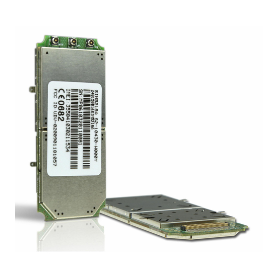
Page 65: View Of The Sim5218E
SIM5218E Hardware Design 6.5 View of the SIM5218E Top View Bottom View Figure 42: Top and Bottom View of SIM5218E 6.6 PIN assignment of board-to-board connector of SIM5218E Table 40 : Connection diagrams Measure Measure Pin No Define Pin No... - Page 66 SIM5218E Hardware Design CAM_CLK CAM_VSYNC CAM_STANDBY CAM_PCLK SPK_P CAM_RESET SPK_N IIC_SDA NC(See Note) EAR_P IIC_SCL NC(See Note) EAR_N POWER_ON 0.1u MIC_N ground 0.1u MIC_P ground RESET HP_MICP GPIO2 HKADC GPIO3 VREG_AUX GPIO4 SD_DATA3 GPIO5 SD_DATA2 SD_CLK SD_DATA1 SD_CMD SD_DATA0 UART_RXD has been pulled down with a 15kR resistor to ground in module.
- Page 67 SIM5218E Hardware Design Contact us: Shanghai SIMCom Wireless Solutions Ltd. Add: SIM Technology Building,No.633,Jinzhong Road,Changning Disdrict, Shanghai P.R. China 200335 Tel: +86 21 3235 3300 Fax: +86 21 3235 3301 URL: www.sim.com/wm SIM5218E_HD_V1.03 11.06.2009...
Need help?
Do you have a question about the SIM5218E and is the answer not in the manual?
Questions and answers