Table of Contents
Advertisement
Advertisement
Table of Contents

Related Manuals for SimCom SIM7000G


Summary of Contents for SimCom SIM7000G
- Page 1 SIM7000G_User Manual_V1.01 Document Title SIM7000G_User Manual...
- Page 2 SIM7000G_User Manual_V1.01 General Notes SIMCom offers this information as a service to its customers to support the application and engineering efforts that use the products designed by SIMCom. The information provided is based on the requirements specifically from the customers. SIMCom has not undertaken any independent search for additional relevant information, including any information that may be in the customer’s...
- Page 3 FCC ID of the module is visible; then an additional permanent label referring to the enclosed module: Contains Transmitter Module FCC ID: 2AJYU- SIM7000G or Contains FCC ID: 2AJYU-SIM7000G must be used. This product is suitable for collocation internal and external antenna.Gain the scope of the...
- Page 4 2014/53/EU Serviceshave been fully fulfilled on our product with indication below: Product Name: LTE CAT-M1(eMTC) and NB-IoT Module Model Name: SIM7000G Brand Name: SIMCom Hardware Version: SIM7000G_V1.03 Software Version: SIM7000G R1529 The following standards have been applied for the investigation of compliance: EN 60950-1:2006+A11:2009+A1:2010+A12:2011+A2:2013 EN 62311-2008 EN 301 489-1 V2.2.0 EN 301 489-3 V2.1.1...
-
Page 5: Table Of Contents
Smart Machine Smart Decision Contents Contents............................... 5 Table Index............................7 Figure Index............................8 Revision History..........................9 Introduction..........................10 Product Outline........................10 Hardware Interface Overview....................11 Hardware Block Diagram..................... 12 Functional Overview......................13 Package Information......................... 15 Pin Assignment Overview....................15 Pin Description........................17 Mechanical Information......................20 Footprint Recommendation....................21 Interface Application.........................22 Power Supply........................ - Page 6 Smart Machine Smart Decision LTE CAT-M1Antenna Design Guide..................41 GNSS............................ 42 4.3.1 GNSS Technical specification..................42 4.3.2 GNSS Application Guide....................43 Electrical Specifications......................45 Absolute maximum ratings....................45 Operating conditions......................45 Operating Mode........................46 5.3.1 Operating Mode Definition....................46 5.3.2 Sleep mode........................47 5.3.3 Minimum functionality mode and Flight mode.............47 Current Consumption......................48 ESD Notes..........................49 SMT Production Guide......................
- Page 7 Smart Machine Smart Decision Table Index Table 1: SIM7000 frequency bands and air interface..................10 Table 2: General features............................. 13 Table 3: Pin definition............................16 Table 4: IO parameters definition........................17 Table 5: Pin description............................17 Table 6: VBAT pins electronic characteristic.......................22 Table 7: Recommended Zener diode list......................23 Table 8: Power on timing and electronic characteristic..................
- Page 8 Smart Machine Smart Decision Figure Index Figure 1: SIM7000 block diagram........................12 Figure 2: Pin assignment overview........................15 Figure 3: Dimensions (Unit: mm)........................20 Figure 4: Footprint recommendation (Unit: mm)....................21 Figure 5: VBAT voltage drop during burst emission (GSM/GPRS)..............22 Figure 6: Power supply application circuit......................
-
Page 9: Revision History
Smart Machine Smart Decision Revision History Data Version Description of change Author Tu Hongjun 2018-08-22 1.00 Original Li Ya SIM7000 _Hardware Design _V1.00 2017-05-23... -
Page 10: Introduction
Product Outline The SIM7000 series modules support LTE CAT-M1、NB-IoT and GPRS/EDGE; The physical dimension of SIM7000G is 24 × 24 × 2.6mm mm. And the physical dimension is compatible with the packaging of SIM900, SIM800 and SIM800F. Table 1: SIM7000G frequency bands and air interface... -
Page 11: Hardware Interface Overview
Smart Machine Smart Decision Hardware Interface Overview The interfaces are described in detail in the next chapters include: Power Supply ● USB Interface ● UART Interface ● SIM Interface ● ● LDO Power Output ● PCM Interface ● I2C Interface ●... -
Page 12: Hardware Block Diagram
Smart Machine Smart Decision Hardware Block Diagram The block diagram of the SIM7000G module is shown in the figure below. Figure 1: SIM7000 block diagram SIM7000 _Hardware Design _V1.00 2017-05-23... -
Page 13: Functional Overview
Smart Machine Smart Decision Functional Overview Table 2: General features Feature Implementation Power supply Power supply voltage 3.0~4.3V Current in sleep mode: 1mA Power saving Current in PSM mode: 9uA Radio frequency bands Please refer to the table 1 Transmitting power LTE CAT-M1power class: 3 (0.25W) LTE CAT-M1CAT M1: 300Kbps (DL) Data Transmission... - Page 14 Smart Machine Smart Decision specifications if the temperature is outside the normal operating temperature range and still within the extreme operating temperature range. SIM7000 _Hardware Design _V1.00 2017-05-23...
-
Page 15: Package Information
Smart Machine Smart Decision Package Information Pin Assignment Overview All functions of the SIM7000G will be provided through 68 pads that will be connected to the customers’ platform. The following Figure is a high-level view of the pin assignment of the SIM7000. - Page 16 Smart Machine Smart Decision Table 3: Pin definition Pin No. Pin Name Pin No. Pin Name PWRKEY BOOT_CFG PCM_CLK PCM_SYNC PCM_DIN PCM_DOUT VDD_EXT NRESET MDM_LOG_TX USB_VBUS USB_DP USB_DM SIM_VDD SIM_DATA SIM_CLK SIM_RST SIM_DET I2C_SDA I2C_SCL GPIO4 GPIO1/UART3_RXD GPIO0/UART3_TXD NETLIGHT GNSS_ANT VBAT VBAT VBAT...
-
Page 17: Pin Description
Smart Machine Smart Decision Pin Description Table 4: IO parameters definition Pin type Description Power input Power output Analog input Analog input/output Bidirectional input /output Digital input Digital output Digital output with high level Digital output with low level Pull up Pull down Table 5: Pin description Default... - Page 18 Smart Machine Smart Decision SIM interface SIM Card data I/O, which has been pulled up via a 10KR SIM_DATA I/O,PU resistor to SIM_VDD internally. Do not pull it up or down externally. All lines of SIM SIM_RST SIM Reset interface should be SIM_CLK SIM clock protected against ESD.
- Page 19 Smart Machine Smart Decision GPIO LED control output as network NETLIGHT status indication. Operating status output. High level: Power on and STATUS firmware ready Low level: Power off Default: GPIO GPIO0 If unused, keep them Optional: UART3_TXD open. Default: GPIO GPIO1 Optional: UART3_RXD GPIO2...
-
Page 20: Mechanical Information
Mechanical Information The following figure shows the package outline drawing of SIM7000. Figure 3: Dimensions (Unit: mm) -
Page 21: Footprint Recommendation
Smart Machine Smart Decision Footprint Recommendation Figure 4: Footprint recommendation (Unit: mm) SIM7000 _Hardware Design _V1.00 2017-05-23... -
Page 22: Interface Application
Smart Machine Smart Decision Interface Application Power Supply Pin 55, pin 56 and pin 57 are VBAT power input. On VBAT pads, the ripple current up to 0.6A typically due to LTE CAT-M1emission burst and up to 2A typically due to GSM/GPRS emission burst (every 4.615ms). It may cause voltage drop. So the power supply for these pads must be able to provide sufficient current up to more than 2A in order to avoid the voltage drop is more than 300mV. -
Page 23: Power Supply Design Guide
Smart Machine Smart Decision 3.1.1 Power Supply Design Guide Make sure that the voltage on the VBAT pins will never drop below 3.0V, even during a transmit burst, when current consumption may rise up to 2A. If the voltage drops below 3.0V, module will be work abnormally. -
Page 24: Voltage Monitor
Smart Machine Smart Decision The following figure shows the linear regulator reference circuit with 5V input and 3.8V output. Figure 7: Linear regulator reference circuit If there is a big voltage difference between input and output for VBAT power supply, or the efficiency is extremely important, then a switching mode power supply will be preferable. -
Page 25: Power On/Power Off/Reset Function
Smart Machine Smart Decision Power on/Power off/Reset Function 3.2.1 Power on SIM7000 can be powered on by pulling the PWRKEY pin to ground. The PWRKEY pin has been pulled up with a diode to 1.8V internally, so it does not need to be pulled up externally. -
Page 26: Power Off
Smart Machine Smart Decision Table 8: Power on timing and electronic characteristic Symbol Parameter Min. Typ. Max. Unit The time of active low level impulse of PWRKEY pin to power on module The time from power-on issue to STATUS pin on(status) output high level(indicating power up ready ) The time from power-on issue to UART port ready... -
Page 27: Reset Function
Smart Machine Smart Decision Table 9: Power off timing and electronic characteristic Time value Symbol Parameter Unit Min. Typ. Max. The active low level time pulse on PWRKEY pin to power off module The time from power-off issue to STATUS pin output low off(status) level(indicating power off )* The time from power-off issue to UART port off... -
Page 28: Uart Interface
Smart Machine Smart Decision Table 10: RESET pin electronic characteristic Symbol Description Min. Typ. Max. Unit The active low level time impulse on RESET pin reset to reset module Input high level voltage Input low level voltage -0.3 UART Interface SIM7000 provides a 7-wire UART (universal asynchronous serial transmission) interface as DCE (Data Communication Equipment). -
Page 29: Ri And Dtr Behavior
Smart Machine Smart Decision The SIM7000 UART is 1.8V voltage interface. If user’s UART application circuit is 3.3V voltage interface, the level shifter circuits should be used for voltage matching. The TXB0108RGYR provided by Texas Instruments is recommended. The following figure shows the voltage matching reference design. -
Page 30: Usb Interface
Smart Machine Smart Decision Normally RI will be kept at a high level until a voice call, then it will output periodic rectangular wave with 5900ms low level and 100ms high level. It will output this kind of periodic rectangular wave until the call is answered or hung up. -
Page 31: Sim Interface
Smart Machine Smart Decision SIM Interface SIM7000 supports both 1.8V and 3.0V SIM Cards. Table 11: SIM electronic characteristic in 1.8V mode (SIM_VDD=1.8V) Symbol Parameter Min. Typ. Max. Unit SIM_V LDO power output voltage 1.75 1.95 High-level input voltage 0.65*SIM_VDD SIM_VDD +0.3 Low-level input voltage -0.3... -
Page 32: Recommended Sim Card Holder
Smart Machine Smart Decision Note: SIM_DATA has been pulled up with a 10KΩ resistor to SIM_VDD in module. A 100nF capacitor on SIM_VDD is used to reduce interference. For more details of AT commands about SIM, please refer to document [1].SIM_CLK is very important signal, the rise time and fall time of SIM_CLK should be less than 40ns, otherwise the SIM card might not be initialized correctly. -
Page 33: Pcm Interface
PCM Interface SIM7000 provides a PCM interface for external codec, which can be used in master mode with short sync and 16 bits linear format. Table 14: PCM format Characteristics Specification Line Interface Format (Fixed) Linear Data length 16bits(Fixed) PCM Clock/Sync Source Master Mode(Fixed) PCM Clock Rate 2 048 KHz (Fixed) - Page 34 Smart Machine Smart Decision Figure 23: Module to external codec timing Table 15: PCM timing parameters Parameter Description Min. Typ. Max. Unit T(sync) PCM_SYNC cycle time – – μs T(synch) PCM_SYNC high level time – – T(syncl) PCM_SYNC low level time –...
-
Page 35: Pcm Application Guide
Smart Machine Smart Decision 3.6.2 PCM Application Guide The following figure shows the external codec reference design. Figure 24: Audio codec reference circuit I2C Interface SIM7000 provides a I2C interface compatible with I2C specification, version 5.0, with clock rate up to 400 kbps. Its operation voltage is 1.8V. The following figure shows the I2C bus reference design. -
Page 36: Other Interface
Smart Machine Smart Decision following figure. Figure 26: NETLIGHT reference circuit Note: The value of the resistor named “R” depends on the LED characteristic. Table 16: NETLIGHT pin status NETLIGHT pin status Module status 64ms ON, 800ms OFF No registered network 64ms ON, 3000ms OFF Registered network 64ms ON, 300ms OFF... -
Page 37: Ldo
Smart Machine Smart Decision Input Range Input serial resistance MΩ – – Note: “AT+CADC” can be used to read the voltage of the ADC pin, for more details, please refer to document [1]. 3.9.2 SIM7000 has a LDO power output named VDD_EXT. The output voltage is 1.8V. Figure 27:Power on sequence of the VDD_EXT Table 18: Electronic characteristic Symbol... -
Page 38: Rf Specifications
Smart Machine Smart Decision RF Specifications LTE CAT-M1 RF Specifications Table 19: Conducted transmission power Frequency BAND Power Min. 23dBm +/-2.7dB <-40dBm 23dBm +/-2.7dB <-40dBm 23dBm +/-2.7dB <-40dBm 23dBm +/-2.7dB <-40dBm 23dBm +/-2.7dB <-40dBm 23dBm +/-2.7dB <-40dBm 23dBm +/-2.7dB <-40dBm 23dBm +/-2.7dB <-40dBm 23dBm +/-2.7dB... - Page 39 Smart Machine Smart Decision Table 21: E-UTRA operating bands E-UTRA UL Freq. DL Freq. Duplex Mode 1920 ~1980 MHz 2110 ~2170 MHz HD-FDD 1850 ~1980 MHz 1930~1990 MHz HD-FDD 1710 ~1785 MHz 1805 ~1880 MHz HD-FDD 1710~1755 MHz 2110 ~2155 MHz HD-FDD 824 ~849 MHz 869 ~894 MHz...
- Page 40 Smart Machine Smart Decision Table 23: CAT-M1 Reference sensitivity (QPSK) E-UTRA Band REFSENS (dBm) Duplex Mode -103 HD-FDD -101 HD-FDD -100 HD-FDD -103 HD-FDD -101.5 HD-FDD -101 HD-FDD -100.5 HD-FDD -103 HD-FDD -100 HD-FDD -100 HD-FDD -103 HD-FDD -103 HD-FDD -100.5 HD-FDD -103...
-
Page 41: Lte Cat-M1Antenna Design Guide
Users should connect antennas to SIM7000’s antenna pads through micro-strip line or other types of RF trace and the trace impedance must be controlled in 50Ω. SIMCom recommends that the total insertion loss between the antenna pads and antennas should meet the following requirements:... -
Page 42: Gnss
Smart Machine Smart Decision Figure 28: Antenna matching circuit (MAIN_ANT) figure 28, the components L101,C106,C107 and R101 or R102 are used for antenna matching, the values of components can only be achieved after the antenna tuning and usually provided by antenna vendor. -
Page 43: Gnss Application Guide
Smart Machine Smart Decision Accuracy (Open Sky): 2.5m (CEP50) TTFF (Open Sky) : Hot start <1s, Cold start<35s Receiver Type: 16-channel, C/A Code GPS L1 Frequency: 1575.42±1.023MHz GLONASS: 1597.5~1605.8 MHz BD: 1559.05~1563.14 MHz Update rate: Default 1 Hz ... - Page 44 Smart Machine Smart Decision In above figures, the components C1, L1 and L2 are used for antenna matching. Usually, the values of the components can only be achieved after antenna tuning and usually provided by antenna vendor. C2 is used for DC blocking. L3 is the matching component of the external LNA, and the value of L3 is determined by the LNA characteristic and PCB layout.
-
Page 45: Electrical Specifications
Smart Machine Smart Decision Electrical Specifications Absolute maximum ratings Absolute maximum rating for digital and analog pins of SIM7000 are listed in the following table: Table 26: Absolute maximum ratings Parameter Min. Typ. Max. Unit Voltage at VBAT -0.5 Voltage at USB_VBUS -0.5 5.85 Voltage at digital pins... -
Page 46: Operating Mode
Smart Machine Smart Decision *Note: These parameters are for digital interface pins, such as GPIOs (including NETLIGHT,STATUS,SIM_DET), I2C, UART, PCM, MDM_LOG_TX and BOOT_CFG. The operating temperature of SIM7000 is listed in the following table. Table 29: Operating temperature Parameter Min. Typ. -
Page 47: Sleep Mode
Smart Machine Smart Decision than normal mode. AT command “AT+CFUN=4” can be used to set the module to flight mode without removing the power supply. In this mode, the RF part Flight mode of the module will not work, but the serial port and USB port are still accessible. -
Page 48: Current Consumption
Smart Machine Smart Decision When SIM7000 is in minimum functionality or flight mode, it can return to full functionality by the AT command “AT+CFUN=1”. Current Consumption The current consumption is listed in the table below. Table 31: Current consumption on VBAT Pins (VBAT=3.8V) GNSS GNSS supply current Tracking Typical: 34mA... -
Page 49: Esd Notes
Smart Machine Smart Decision ESD Notes SIM7000 is sensitive to ESD in the process of storage, transporting, and assembling. When SIM7000 is mounted on the users’ mother board, the ESD components should be placed beside the connectors which human body may touch, such as SIM card holder, audio jacks, switches, keys, etc. The following table shows the SIM7000 ESD measurement performance without any external ESD component. -
Page 50: Smt Production Guide
Smart Machine Smart Decision SMT Production Guide Top and Bottom View of SIM7000 Figure 31: Top and bottom view of SIM7000 SIM7000 _Hardware Design _V1.00 2017-05-23... -
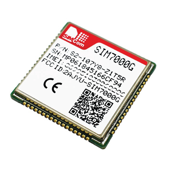
Page 51: Label Information
Smart Machine Smart Decision Label Information Figure 32: Label information Table 33: The description of label information Description LOGO No.1 Pin Project name Product code Serial number International mobile equipment identity QR code SIM7000 _Hardware Design _V1.00 2017-05-23... -
Page 52: Typical Smt Reflow Profile
Smart Machine Smart Decision Typical SMT Reflow Profile SIMCom provides a typical soldering profile. Therefore the soldering profile shown below is only a generic recommendation and should be adjusted to the specific application and manufacturing constraints. Figure 33: The ramp-soak-spike reflow profile of SIM7000 Note: For more details about secondary SMT, please refer to the document [21]. -
Page 53: Stencil Foil Design Recommendation
Smart Machine Smart Decision time limit specified on the label. NOTE: IPC / JEDEC J-STD-033 standard must be followed for production and storage. Stencil Foil Design Recommendation The recommended thickness of stencil foil is 0.15mm. SIM7000 _Hardware Design _V1.00 2017-05-23... -
Page 54: Packaging
Smart Machine Smart Decision Packaging tray packaging SIM7000 module support tray packaging (default packaging). Figure 34: packaging diagram Module tray drawing: SIM7000 _Hardware Design _V1.00 2017-05-23... - Page 55 Smart Machine Smart Decision Figure 35: Tray drawing Table 35: Tray size Length(±3mm) Width(±3mm) Module number 242.0 161.0 Small carton drawing: Figure 36: Small carton drawing Table 36: Small Carton size Length(±10mm) Width(±10mm) Height(±10mm) Module number 20*20=400 Big carton drawing: Figure 37: Big carton drawing SIM7000 _Hardware Design _V1.00 2017-05-23...
- Page 56 Smart Machine Smart Decision Table 37: Big Carton size Length(±10mm) Width(±10mm) Height(±10mm) Module number 400*4=1600 SIM7000 _Hardware Design _V1.00 2017-05-23...
-
Page 57: Appendix
Appendix A. Reference Design Refer to < SIM7000 Reference Design V1.01> for the details. Figure 38: Reference design... -
Page 58: Related Documents
Smart Machine Smart Decision B. Related Documents Table 38: Related Documents Title Description SIM7X00 Series_AT AT Command Manual Command Manual_V1.xx ITU-T Draft new Serial asynchronous automatic dialing and control recommendationV.25ter Digital cellular telecommunications (Phase 2+); AT command GSM 07.07 set for GSM Mobile Equipment (ME) GSM 07.10 Support GSM 07.10 multiplexing protocol Digital cellular telecommunications (Phase 2+);... - Page 59 Smart Machine Smart Decision 2010+A12:2011+A2:2013 Digital cellular telecommunications system (Release 5); [18] 3GPP TS 51.010-1 Mobile Station (MS) conformance specification SIM7000 _Hardware Design _V1.00 2017-05-23...
-
Page 60: Terms And Abbreviations
Smart Machine Smart Decision C. Terms and Abbreviations Table 39: Terms and Abbreviations Abbreviation Description Analog-to-Digital Converter Antenna Reference Point Bit Error Rate BeiDou Base Transceiver Station Coding Scheme Circuit Switched Data Clear to Send Digital-to-Analog Converter Discontinuous Reception Digital Signal Processor Data Terminal Equipment (typically computer, terminal, printer) Data Terminal Ready Discontinuous Transmission... - Page 61 Smart Machine Smart Decision Personal Communication System, also referred to as GSM 1900 Radio Frequency Root Mean Square (value) Real Time Clock Subscriber Identification Module Short Message Service SMPS Switched-mode power supply TDMA Time Division Multiple Access Terminal Equipment, also referred to as DTE Transmit Direction UART Universal Asynchronous Receiver &...
-
Page 62: Safety Caution
Smart Machine Smart Decision D. Safety Caution Table 40: Safety Caution Marks Requirements When in a hospital or other health care facility, observe the restrictions about the use of mobiles. Switch the cellular terminal or mobile off, medical equipment may be sensitive and not operate normally due to RF energy interference. - Page 63 Smart Machine Smart Decision Contact us: Shanghai SIMCom Wireless Solutions Ltd. Add: SIM Technology Building, No.633, Jinzhong Road, Changning District, Shanghai P.R. China 200335 Tel:+86 21 3235 3300 Fax:+86 21 3235 3020 URL:www.simcomm2m.com SIM7000 _Hardware Design _V1.00 2017-05-23...
Need help?
Do you have a question about the SIM7000G and is the answer not in the manual?
Questions and answers