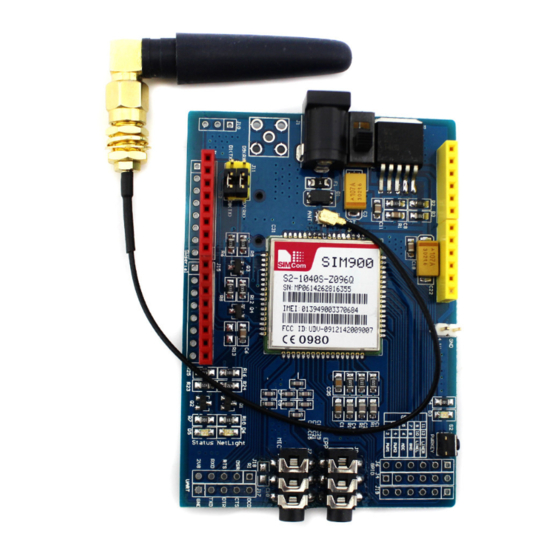
SimCom SIM900 Reference Design Manual
Hide thumbs
Also See for SIM900:
- Hardware design (59 pages) ,
- User manual (11 pages) ,
- Operation user's manual (10 pages)
Table of Contents
Advertisement
Quick Links
Download this manual
See also:
User Manual
Advertisement
Table of Contents

Subscribe to Our Youtube Channel
Summary of Contents for SimCom SIM900
- Page 1 SIM900 Reference Design Guide SIM900_AN_ Reference Design Guide_V1.01...
- Page 2 Furthermore, system validation of this product designed by SIMCom within a larger electronic system remains the responsibility of the customer or the customer’s system integrator. All specifications supplied herein are subject to change.
-
Page 3: Table Of Contents
SIM900 Reference Design Guide Notes Contents Version history..........................4 1. Introduction...........................5 1.1 References Document ......................5 2 Application Interface........................2 2.1 Power Supply Design ......................2 2.1.1 VBAT design ......................2 2.1.2 Battery Charge design ....................3 2.1.3 PWRKEY ON/OFF design..................4 2.1.4 Reset design........................5 2.1.5 RTC backup design ....................5 2.2. -
Page 4: Version History
SIM900 Reference Design Guide Notes Version history Date Version Description of change Author 2010-01-01 1.01 First Release Zhou Qiang SIM900_AN_Reference Design Guide_V1.01 01.27.2010... -
Page 5: Introduction
SIM900 Reference Design Guide Notes 1 Introduction This document describes how to design peripheral interface of SIMCOM module providing in your application. 1.1 References Document Document name Remark SIM900_ATC SIM900 AT command Set SIM900_HD SIM900 Hardware Specification SIM900_EVB_UGD SIM900 EVB User Guide... -
Page 6: Application Interface
3.4V, and the module will auto power down. Typically, VBAT can be set to 4V. SIM900 can be used in a wide range of application, the power supply design is deeply depending on the power source. -
Page 7: Battery Charge Design
470uF. 2.1.2 Battery Charge design SIM900 do not support the battery charge function. When the Li-ion battery is needed in the application, a charger IC will be implemented. If the battery is only for backup (the AC adaptor is mostly powered), we suggest you choose a charger IC with power-path management for battery lifespan. -
Page 8: Pwrkey On/Off Design
Figure 3: Battery Charge Supply 2.1.3 PWRKEY ON/OFF design The simplest way to turn on/off SIM900 is driving the PWRKEY to a low level for 1S then release. PWRKEY pin has been pulled up to 3V inside the module. Following figure is the recommended connection with a NPN transistor. -
Page 9: Reset Design
SIM900 support the reset function, when the MCU find the module is in an abnormal state, SIM900 can be restarted by pulling the RESET pin to ground for a typical 50uS. Reset is a noise sensitivity pin, it should be kept away from the high speed signal line (eg. clock) when layout. -
Page 10: Gpio Selection
NETLIGHT is a net status indicator. It can drive a transistor to control a LED which will blink slowly or quickly according to different states. Please note that it can’t drive a LED directly. Both STATUS and NETLIGHT is dedicated in SIM900, they can not be used as a GPIO for the customer. -
Page 11: Gpio
2.3.2 GPIO SIM900 serves 12 GPIO which can be controlled by the customer. As a GPI, the status can be read by the AT command and as a GPO, it also can be controlled by the AT command. The customer can use this GPIO to achieve some simple control. -
Page 12: Referenced Circuit Of Headset Design
SIM900 Reference Design Guide Notes 2.4.1 Referenced circuit of headset design Figure 9: Referenced circuit of headset 2.4.2 Referenced circuit of hand free design Figure 10: Referenced circuit of audio PA Antenna matching circuit design Because the module is working under 50ohm system in RF part, so, to get the best RF performance, the SMT module’s load impedance should be tuned to 50ohm. -
Page 13: Sim Card Interface
The SIM_PRESENCE pin is used for detecting the SIM card. There is a 100k pull down resistor in SIM900 module. So the R110 should not be bigger than 10K. If you don’t use the SIM card detection function, you can let the SIM_PRESENCE pin open or connect to the GND. -
Page 14: Esd Protection
SIM900 Reference Design Guide Notes Figure 12: Reference circuit with 8-pin SIM card holder 2.7 ESD protection It is suggested that it’s better to do some ESD protection in your application to improve the ESD character of the module, especially for the signal connecting to external interface, for example, MIC, SPK,PWRKEY,VBAT,DBG,SIMCARD. - Page 15 SIM900 Reference Design Guide Notes RF trace between SMT module RF pad with the RF test connector, RF trace between RF test connector with the antenna matching circuit, RF trace between the antenna matching circuit with the antenna feed PAD all should be controlled to 50 Ohm 10) All layers under the antenna feed pad should be copper keep out.
- Page 16 SIM900 Reference Design Guide Notes Contact us: Shanghai SIMCom Wireless Solutions Ltd. Add: Building A,SIM Technology Building,No.633,Jinzhong Road,Changning District, Shanghai,P. R. China 200335 Tel: +86 21 3235 3300 Fax: +86 21 3235 3301 URL: www.sim.com/wm SIM900_AN_Reference Design Guide_V1.01 01.27.2010...


Need help?
Do you have a question about the SIM900 and is the answer not in the manual?
Questions and answers