Table of Contents
Advertisement
Quick Links
Advertisement
Table of Contents

Subscribe to Our Youtube Channel
Related Manuals for SimCom SIM7200


Summary of Contents for SimCom SIM7200
- Page 1 SIM7200 Mini PCIe Module Hardware Guide_V1.01...
- Page 2 Control ID General Notes SIMCom offers this information as a service to its customers, to support application and engineering efforts that use the products designed by SIMCom. The information provided is based upon requirements specifically provided to SIMCom by the customers. SIMCom has not undertaken any independent search for additional relevant information, including any information that may be in the customer’s possession.
-
Page 3: Table Of Contents
Power Supply ............................21 Power Saving Mode..........................22 4.2.1. Minimum Functionality Mode and Sleep Mode ................. 22 4.2.2. Wake Up SIM7200 from Sleep Mode ....................23 USB 2.0 ..............................23 4.3.1 USB Port Specification ........................23 4.3.2 Firmware Update ..........................24 4.3.3... -
Page 4: Sim7200-Pcie_ Hardware_Design _V1.01
Smart Machine Smart Decision III. Terms and Abbreviations ........................41 Safety Caution ............................43 Contact us:................................44 URL: www.simcomm2m.com ..........................44 SIM7200-PCIe_ Hardware_Design _V1.01 2016-05-19... - Page 5 Smart Machine Smart Decision Table Index TABLE 1: SIM7200 KEY FEATURES ..........................9 TABLE 2: SIM7200 SERIES FREQUENCY BANDS ....................10 TABLE 3: CODING SCHEMES AND MAXIMUM NET DATA RATES OVER AIR INTERFACE ......11 TABLE 4: OPERATING MODE ............................13 TABLE 5: PCI EXPRESS MINI CARD CONNECTOR PIN DESCRIPTION ...............
- Page 6 FIGURE 6: DIMENSIONS OF PCI EXPRESS CONNECTOR ..................18 FIGURE 7: DIMENSIONS OF LATCH FOR PCI EXPRESS CONNECTOR ............... 18 FIGURE 8: STEP 1 OF INSTALLING SIM7200 ON THE MAIN BOARD ..............19 FIGURE 9: STEP 2 OF INSTALLING SIM7200 ON THE MAIN BOARD ..............19 FIGURE 10: STEP 3 OF INSTALLING SIM7200 ON THE MAIN BOARD ..............
- Page 7 Smart Machine Smart Decision Date Version Description of change Author Song.jialin 2016-3-9 1.01 Li .Ya SIM7200-PCIe_ Hardware_Design _V1.01 2016-05-19...
-
Page 8: Introduction
Smart Machine Smart Decision 1. Introduction Scope of this document is to give a detail design guide of the SIMCom SIM7200 series, this document can help user to quickly understand SIM7200 interface specifications, electrical and mechanical details. With the help of this document and other SIM7200 application notes, user guide, users can apply SIM7200 in various applications quickly. -
Page 9: Table 1: Sim7200 Key Features
Weight: 11g Memory capacity 2Gbit DDR2 RAM and 4Gbit NAND flash. Firmware upgrade Firmware upgrade over USB interface In this document, the entire radio band configuration of SIM7200 and SIM7200SA are described in the following table. SIM7200-PCIe_ Hardware_Design _V1.01 2016-05-19... -
Page 10: Table 2: Sim7200 Series Frequency Bands
LTE TDD B38 LTE TDD B39 LTE-TDD LTE TDD B40 LTE TDD B41 (100M BW) Note: Operating bandwidth frequencies of LTE TDD B41 for SIM7200 and SIM7200SA is 100MHz, from 2555MHz to 2655MHz SIM7200-PCIe_ Hardware_Design _V1.01 2016-05-19... -
Page 11: Table 3: Coding Schemes And Maximum Net Data Rates Over Air Interface
Category 2 1.2Mbps 16QAM,QPSK Category 3 1.8Mbps 16QAM,QPSK Category 4 1.8Mbps 16QAM,QPSK Category 5 3.6Mbps 16QAM,QPSK Category 6 3.6Mbps 16QAM,QPSK Category 7 7.2Mbps 16QAM,QPSK Category 8 7.2Mbps 16QAM,QPSK Category 9 10.2Mbps 16QAM,QPSK Category 10 14.4Mbps 16QAM,QPSK SIM7200-PCIe_ Hardware_Design _V1.01 2016-05-19... - Page 12 Category 2 50Mbps QPSK/16QAM/64QAM Category 3 100Mbps QPSK/16QAM/64QAM Category 4 150Mbps QPSK/16QAM/64QAM LTE-FDD device category Max data rate(peak) Modulation type (Uplink) Category 1 5Mbps QPSK/16QAM Category 2 25Mbps QPSK/16QAM Category 3 50Mbps QPSK/16QAM Category 4 50Mbps QPSK/16QAM SIM7200-PCIe_ Hardware_Design _V1.01 2016-05-19...
-
Page 13: Operating Mode
The power consumption in this mode is lower than normal mode. 2.2. Functional Diagram Figure 2 shows the functional diagram of the SIM7200 module, the major functional units of SIM7200 including the following parts: ... -
Page 14: Figure 2: Sim7200 Functional Diagram
Smart Machine Smart Decision Diversity/Main/GNSS NAND(2Gb) DDR2(1Gb) GNSS PCM/I2C/GPIO GSM/EDGE/GPRS SSBI HSUSB TRANSCEIVER Baseband USIM WTR1625L Switch Module WAKE HOST WWAN DISABLE LTE/WCDMA MDM9625 LED_WWAN TRANSCEIVER Control RESET PMIC 3.3V PM8019 Switch Figure 2: SIM7200 functional diagram SIM7200-PCIe_ Hardware_Design _V1.01 2016-05-19... -
Page 15: Sim7200 Mini Pcie Interface
Smart Machine Smart Decision 2.3. SIM7200 Mini PCIe Interface Table 5: PCI Express Mini Card Connector Pin Description Comment Comment Description Description MICP Audio input 3.3V power supply MICN Audio input Ground EAR_P Audio output Not connected Power source EAR_N... -
Page 16: Package Information
The Mini PCIe Adapter adopts a standard Mini PCI Express connector that has 52 pins and complies with the PCI Express Mini Card Electromechanical Specification Revision 1.2. Pin Out Diagram The following figure shows the PIN sequence of SIM7200: Figure 3: SIM7200-PCIe pin out Diagram SIM7200-PCIe_ Hardware_Design _V1.01... -
Page 17: Package Dimensions
Smart Machine Smart Decision Package Dimensions Figure 4: Dimensions of SIM7200-PCIe (Unit: mm) Figure 5: Detail dimensions of golden finger Please refer to PCI Express Mini Card Electromechanical Specification Revision 1.2 for package dimension details. SIM7200-PCIe_ Hardware_Design _V1.01 2016-05-19... -
Page 18: Mini Pci Express Connector And Latch
Smart Machine Smart Decision Mini PCI Express Connector and Latch SIM7200 should equip to the edge card connector and lock down by the Latch, this chapter takes the Molex 67910-0002 and 48099-4000 as an example. The figure 6 shows the PCI Express connector dimensions:... -
Page 19: Installing Sim7200 On Main Board
Smart Machine Smart Decision Installing SIM7200 on main board Step 1: Insert SIM7200 into the Mini PCI Express connector on the main board. Figure 8: Step 1 of installing SIM7200 on the main board Step 2: Press downwards to fix SIM7200 Adapter in the module slot. -
Page 20: Removing Sim7200 From Main Board
Step 1: Disconnect the antenna cables from SIM7200 cables. Figure 11: Step 1 of removing SIM7200 from the main board Step 2: Push the two clips to release SIM7200 from the slot. Figure 12: Step 2 of removing SIM7200 from the main board Step 3: Push SIM7200 from the direction as following figure shows. -
Page 21: Application Interface
Power Supply The recommended power supply of SIM7200 is 3.3V and the voltage ranges from 3.2 V to 3.6 V. The SIM7200 has 4 power pins and 13 Ground pins, to ensure the SIM7200 module works normally, all the pins must be connected. -
Page 22: Power Saving Mode
SIM7200 stops working, and module has no on air or audio activity required. In sleep mode, SIM7200 can still receive paging or SMS from network. Note: SIM7200 could enter sleep mode if the host CPU supports USB suspend mode, otherwise it could not enter sleep mode. -
Page 23: Wake Up Sim7200 From Sleep Mode
Currently SIM7200 supports the USB suspend and resume mechanism which can help to save power. If no transaction is on USB bus, SIM7200 will enter suspend mode. When some events such as voice call or receiving SMS happen, SIM7200 will resume normal mode automatically. -
Page 24: Firmware Update
Note: SimTech HS-USB PCM Voice function is under development. 4.3.2 Firmware Update If users need to upgrade through USB port, it is necessary to power on SIM7200 first, and then connect USB_DP, USB_DN, GND to host device. 4.3.3 High-speed USB Layout Guide Lines This section summarize the guidelines for designing controlled-impedance, high-speed USB PCBs to comply with the USB specification. -
Page 25: Figure 16: 8 Pin Usim Card Holder Reference Circuit
Avoid routing the USIM_CLK and USIM_DATA lines in parallel and distances over 2 cm, the cross-coupling of these lines can cause failures; The rise time of USIM_CLK and USIM_DATA should be less than 1μs, user should keep low SIM7200-PCIe_ Hardware_Design _V1.01 2016-05-19... -
Page 26: I2C Interface
holder; Add TVS to protect the USIM card and SIM7200 IC, but the parasitic capacitance should not exceed 50pF. Customer should decide whether the TVS diode is necessary depending on the application, mechanical enclosure, and USIM connector design. -
Page 27: Gpio Interface
4.6 GPIO Interface SIM7200 provides 2 GPIO pins. The output voltage level of the GPIO can be set by AT command “AT+ SGPIO”. The input voltage level of the GPIO can also be read by AT command “AT+ SGPIO”. For more details, please refer to document [1]. -
Page 28: W_Disable
Figure 19: Recommend circuit of PERST# 4.8 W_DISABLE# The W_DISABLE# pin controls SIM7200 to enter or exit the airplane mode, when the W_DISABLE# signal is asserted, all radios would be disabled. When the W_DISABLE# signal is not asserted, the radio may transmit if it was not disabled by other means such as software. -
Page 29: Led_Wwan
Smart Machine Smart Decision 4.9 LED_WWAN# LED_WWAN# is an Open drain active low signal; this signal is used to allow SIM7200 to provide network status via LED which will be provided by the host. Table 17: Network Status Indication Pin Status... -
Page 30: Rf Specifications
When choosing antennas, customer should pay attentions to the connector on antenna that should match with the connector on the module. The dimension of the connector on SIM7200 is 2.6*2.6*1.25mm, which is from Hirose, and the part number is U.FL-R-SMT (10), Use KLC-1401 (www.lccable.com) to attach antennas to connection points on the module, as shown in Figure 18, likewise, customer can choose other vendor if the component’s size match with U.FL-R-SMT... -
Page 31: The Antenna Specifications
Smart Machine Smart Decision The Antenna Specifications Recommended antenna characteristics of SIM7200 are described by following two tables. Table 18: Recommended Passive Antenna Characteristics Passive Recommended standard Direction Omni directional Gain > -3dBi (Avg) Input impedance 50 ohm > 50 %... -
Page 32: Electrical, Reliability And Radio Characteristics
Table 22: USIM Card Interface Characteristics Symbol Parameter Type Unit USIM_VDD=1.8V 1.35 USIM_VDD=2.85V 2.85 USIM_RST USIM_VDD=1.8V 0.45 USIM_VDD=2.85V 0.45 USIM_VDD=1.8V 1.35 USIM_VDD=2.85V 2.85 USIM_CLK USIM_VDD=1.8V 1.35 USIM_VDD=2.85V 2.85 USIM_VDD=1.8V USIM_VDD=2.85V 1.85 3.15 USIM_DATA USIM_VDD=1.8V USIM_VDD=2.85V 1.85 3.15 USIM_VDD=2.85V 1.35 SIM7200-PCIe_ Hardware_Design _V1.01 2016-05-19... -
Page 33: Usim_Vdd Characteristics
PCL2 CH698 <450mA,Typical 400mA DCS1900 PCL2 CH661 <450mA,Typical 390mA DATA mode, EDGE( 3Rx, 2 Tx ) CLASS 12 MCS9 GSM 850 PCL8 CH189 <330mA,Typical 260mA GSM 900 PCL8 CH62 <330mA,Typical 270mA DCS1800 PCL2 CH698 <220mA,Typical 260mA SIM7200-PCIe_ Hardware_Design _V1.01 2016-05-19... - Page 34 CH21100 10dBm Typical 310mA Band 7 CH21100 10dBm Typical 320mA CH21100 10dBm Typical 360mA CH21100 10dBm Typical 365mA 1.4M CH21625 10dBm Typical 260mA CH21625 10dBm Typical 260mA Band 8 CH21625 10dBm Typical 260mA CH21625 10dBm Typical 270mA SIM7200-PCIe_ Hardware_Design _V1.01 2016-05-19...
-
Page 35: Electro-Static Discharge
CH39150 10dBm Typical 250mA CH39150 10dBm Typical 250mA Note: In above table the current consumption value is the typical one of the SIM7200 module tested in laboratory. In the mass production stage, there may be differences among each individual. Electro-Static Discharge SIM7200-PCIe is an ESD sensitive component, so more attention should be paid to the procedure of handling and packaging. -
Page 36: Conducted Receive Sensitivity
LTE-FDD B40 23dBm +2.7dB -50dBm ±5dB LTE-FDD B41 23dBm +2.7dB -50dBm ±5dB 6.7.2 Conducted Receive Sensitivity The following table shows conducted receiving sensitivity of SIM7200-PCIe. Table 27: Conducted Receive Sensitivity Frequency Receive sensitivity GSM850 < -108dBm E-GSM900 < -108dBm DCS1800 <... -
Page 37: Supported Band
WCDMA 2100 2110~2170 MHz 1920~1980 MHz WCDMA1900 1930~1990 MHz 1850~1910 MHz 869 ~894 824 ~849 WCDMA 850 925 ~960 880 ~915 WCDMA 900 TDSCDMA 1900 1880~1920 MHz 1880~1920 MHz TDSCDMA 2000 2010~2025 MHz 2010~2025 MHz LTE BAND SIM7200-PCIe_ Hardware_Design _V1.01 2016-05-19... - Page 38 Smart Machine Smart Decision LTE Operating frequencies are shown in following table 32. Note: Operating frequencies of LTE TDD B41 for SIM7200 is 100MHz BW, 2555~2655 1574.4 ~1576.44 MHz GPS L1 BAND 1598 ~1606 MHz GLONASS Table32: E-UTRA operating bands...
- Page 39 Smart Machine Smart Decision 1910 MHz~1930 MHz 1910 MHz~1930 MHz 2570 MHz~2620 MHz 2570 MHz~2620 MHz 1880 MHz~1920 MHz 1880 MHz~1920 MHz 2300 MHz~2400 MHz 2300 MHz~2400 MHz 2496 MHz~2690 MHz 2496 MHz~2690 MHz SIM7200-PCIe_ Hardware_Design _V1.01 2016-05-19...
-
Page 40: Appendix
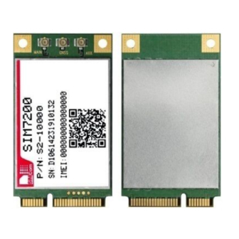
Smart Machine Smart Decision 7. Appendix I. SIM7200-PCIe Top and Bottom View Figure 23: SIM7200-PCIe top and bottom View II. Related Documents Table 28: Related Documents Document name Remark SIMCOM_SIM7200_ATC_EN_ V1.XX.doc AN_SIM7200_TCPIP TCP/IP Applications User Manual Express Mini Card Electromechanical Specification Revision 1.2... -
Page 41: Iii. Terms And Abbreviations
Inter-Integrated Circuit IMEI International Mobile Equipment Identity Light-emitting Diode Low Noise Amplifier Li-ion Lithium-Ion Long Term Evolution Multiple-chip Package MIMO Multi-Input Multi-Output Mobile Originated Mobile Station (GSM engine), also referred to as TE Mobile Terminated Not Connect SIM7200-PCIe_ Hardware_Design _V1.01 2016-05-19... - Page 42 USIM last dialing phonebook (list of numbers most recently dialed) Mobile Equipment list of unanswered MT calls (missed calls) USIM (or ME) own numbers (MSISDNs) list Mobile Equipment list of received calls USIM phonebook Not connect SIM7200-PCIe_ Hardware_Design _V1.01 2016-05-19...
-
Page 43: Iv. Safety Caution
(e.g. lock functions, fixed dialing etc.). You may have to deactivate those features before you can make an emergency call. Also, some networks require that a valid USIM card be properly inserted in the cellular terminal or mobile. SIM7200-PCIe_ Hardware_Design _V1.01 2016-05-19... -
Page 44: Contact Us
Smart Machine Smart Decision Contact us: Shanghai SIMCom Wireless Solutions Ltd. Add: SIM Technology Building, No.633,Jinzhong Road, Changning District, Shanghai P.R. China 200335 Tel: +86 21 3235 3300 Fax: +86 21 3235 3301 www.simcomm2m.com URL: SIM7200-PCIe_ Hardware_Design _V1.01 2016-05-19...
Need help?
Do you have a question about the SIM7200 and is the answer not in the manual?
Questions and answers