Table of Contents
Advertisement
Quick Links
Advertisement
Table of Contents

Related Manuals for SimCom SIM5360A EVB


Summary of Contents for SimCom SIM5360A EVB
- Page 1 Development Kit Manual SIM5360A_EVB_User Guide_V1.02...
- Page 2 SIM5360A_EVB_User Guide_V1.01 General Notes SIMCOM offers this information as a service to its customers, to support application and engineering efforts that use the products designed by SIMCOM. The information provided is based upon requirements specifically provided to SIMCOM by the customers. SIMCOM has not undertaken any independent search for additional relevant information, including any information that may be in the customer’s possession.
-
Page 3: Table Of Contents
FIGURE 8: SERIAL PORT ........................13 FIGURE 9: STATUS LED ........................13 FIGURE 10: USB INTERFACE ......................14 FIGURE 11: SWITCH INTERFACE ..................... 15 FIGURE 12: IO INTERFACE ........................ 16 FIGURE 13: SD CARD SOCKET ......................18 SIM5360A EVB User Guide 03.18.2014... -
Page 4: Version History
TABLE 10: IO INTERFACE ........................17 TABLE 11: SD CARD SOCKET ......................18 Version History Data Version Description of change Author 2014-01-22 1.01 Origin Libing 2014-03-18 1.02 Update to using SIM5360A-EVB V1.03 for description Libing Add UART2 to USB circuit SIM5360A EVB User Guide 03.18.2014... -
Page 5: Overview
Smart Machine Smart Decision 1 Overview This document gives the usage of SIM5360A EVB, user can get useful information about the SIM5360A EVB quickly through this document. The Debug board is designed for customer to design their own applications by using the 3G module SIM5360 easily. -
Page 6: Sim5360 Evb
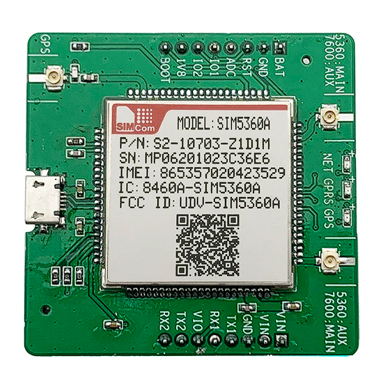
Smart Machine Smart Decision 2 SIM5360A EVB SIM5360A EVB User Guide 03.18.2014... -
Page 7: Figure 1: Evb View
S: SIM5360A JTAG test point T: Adapter connector U: DC LDO V: UART interface for AT command transmitting, data exchanging W: Handset interface(RJ-11) X: Audio codec (WM8960) Y: MicroUSB interface for SIM5360A (UART2 to USB, IC is Silabs Cp2103) SIM5360A EVB User Guide 03.18.2014... - Page 8 Smart Machine Smart Decision The following figure shows block diagram of SIM5360A EVB. All hardware Sub-interfaces included in SIM5360A EVB are described in detail in following chapters. SIM5360A EVB User Guide 03.18.2014...
-
Page 9: Evb Accessories
Input Impedance (Ω): 50 Polarization Type: Vertical Connector Type: SMA C: USB cable D: 5V DC adapter E: GPS/GLONASS antenna F: DIV antenna NOTE: The maximum gain of the RF antenna gain should not exceed 1dBi for end-users. SIM5360A EVB User Guide 03.18.2014... -
Page 10: Accessory Interface
This board could be powered by USB bus. User should connect the USB pin. USB_VBAT is the USB power out.If user wants to use USB VBUS to power up the module, please connect connector VBAT with connector USB_VBAT as following figure shows.and disconnect Adapter_VBAT. SIM5360A EVB User Guide 03.18.2014... -
Page 11: Audio Interface
Negative microphone output Speaker interface: Please refer Figure 1. Pin 1 and Pin 2 is the SPK_M and SPK_P on J501. NOTE: Audio cable must be away from the RF antenna, otherwise TDD noise may be occurred. SIM5360A EVB User Guide 03.18.2014... -
Page 12: Sim Card Interface
USIM Card Power output automatic V_USIM output on USIM mode,one is 3.0V±10%, another is 1.8V±10%. Current is about 10mA. USIM_RESET USIM Card Reset USIM_CLK USIM Card Clock Ground SIM_VPP Not connect USIM_DATA USIM Card data I/O SIM5360A EVB User Guide 03.18.2014... -
Page 13: Antenna Interface
Figure 6: Main and diversity Antenna connector Figure 7 :GPS Antenna connector SIMCom strongly recommends additional matching components between the antenna and the RF output of SIM5360 RF PAD (Main: pin 59; Diversity: PIN 82; GPS: pin 79; ) for the application including an antenna. -
Page 14: Rs232 Interface
Table 7: Network status LED D301 Status Module Status Module is not running Module is running, or voice call is connected Module find the network and registered 800ms On/ Off Data communication 200ms On/ Off SIM5360A EVB User Guide 03.18.2014... -
Page 15: Usb Interface
ADAPTER power indicator D202 USB power indicator 4.7 USB interface Figure 10: USB Interface It is a normal 4Pin USB connector. Table 8: USB interface Signal Description USB_VBUS USB_DM D+ line USB_ DP D- line Ground SIM5360A EVB User Guide 03.18.2014... -
Page 16: Switch Interface
Figure 11: Switch Interface Table 9: Switch interface Switch Signal Description RS232 chip SHUTDOWN UART switch GPIO4 RF switch (S301) ON : Normal mode OFF : Flight mode RESET Reset the module PWRER_ON Power on the module SIM5360A EVB User Guide 03.18.2014... -
Page 17: Io Interface
Smart Machine Smart Decision 4.9 IO interface Figure 12: IO Interface SIM5360A EVB User Guide 03.18.2014... -
Page 18: Table 10: Io Interface
General input pin for module wake up interrupt. It PCM_DIN/GPIO0 also can be multiplexed as the PCM_DIN pin. General input pin. It also can be multiplexed as the PCM_SYNC/GPIO2 PCM_SYNC pin. PCM_CLK/GPIO3 General output pin. It also can be multiplexed as the SIM5360A EVB User Guide 03.18.2014... -
Page 19: Sd Card Interface
Table 11: SD card socket Signal Input/Output Description SD_D2 Data line 2 SD_D3 Data line 3 SD_CMD Command line VREG_SDCC Power supply for SD card SD_CLK Clock line Ground SD_D0 Data line 0 SD_D1 Data line 1 SIM5360A EVB User Guide 03.18.2014... -
Page 20: Uart2 To Microusb Interface
Figure 14: MicroUSB interface J401 is 5 pins standard MicroUSB interface. It can be connected to a PC directly. The following figure is the uart to USB circuit of SIM5360-EVB. Figure 15: Uart to USB circuit SIM5360A EVB User Guide 03.18.2014... -
Page 21: Evb And Accessory Equipment
USB_VBAT pin and VBAT pin on the EVB board, and make sure that RF control switch is set to ON. Firstly insert the sim card and connect the antenna, then connect the PC with USB-to-USB cable and press the Power_ON button for one second, then SIM5360 will start running. SIM5360A EVB User Guide 03.18.2014... -
Page 22: Installing Driver
“ATI”, it should display product identification information. (4) If user want to use USB to USB cable, user need to connect the cable to USB port of the module and the computer, then follow step 1~3. SIM5360A EVB User Guide 03.18.2014... -
Page 23: Downloading
Figure 17: USB interface update procedure 6.5 Turning off Press the POWER_ON for about 1 second, SIM5360 module will be turned off. NOTE: If user uses USB to power on the module, just disconnect the USB cable to turn off. SIM5360A EVB User Guide 03.18.2014... - Page 24 Smart Machine Smart Decision Contact us: Shanghai SIMCom Wireless Solutions Ltd. Add: Building A,SIM Technology Building,No.633,Jinzhong Road,Changning Disdrict,Shanghai P.R. China 200335 Tel: +86-21-3252 3300 Fax: +86-21-3252 3301 URL: www.sim.com SIM5360A EVB User Guide 03.18.2014...
Need help?
Do you have a question about the SIM5360A EVB and is the answer not in the manual?
Questions and answers