Advertisement
Table of Contents
- 1 Table of Contents
- 2 Application
- 3 Product Description
- 4 Limits of Application
- 5 Technical Specification
- 6 Pump Connections
- 7 Pre Installation Assembly
- 8 Siting of the Pump/Pipework
- 9 Electrical Installation
- 10 Noise
- 11 Commissioning
- 12 Maintenance
- 13 Storage
- 14 Trouble Shooting Guide
- 15 Environment Protection
- Download this manual
Advertisement
Table of Contents

Related Manuals for Stuart Turner BOOSTAMATIC 330


Summary of Contents for Stuart Turner BOOSTAMATIC 330
- Page 1 BOOSTAMATIC PUMPS OPERATING INSTRUCTIONS Please leave this instruction booklet with the pump as it contains maintenance and safety information.
-
Page 2: Table Of Contents
WARNING AGAINST MISUSE This pump set must not be used for any other application without the written consent of Stuart Turner Limited and, in particular, must not be connected directly to the mains water supply or used outside the conditions specified in the limits of application. -
Page 3: Product Description
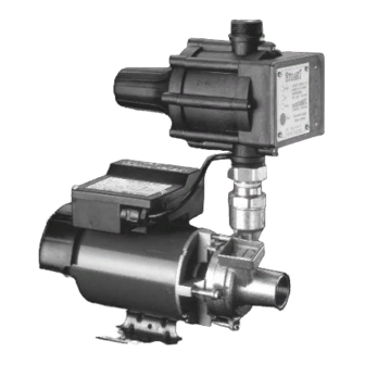
PRODUCT DESCRIPTION Electric motor driven pump complete with automatic control module consisting of flow switch, pressure switch, pressure vessel and electronic control. Motor Diver Range: Class 'B' insulation, continuously rated and encapsulated with a (304) stainless steel casing. Jet Range: Class ‘B’ insulation, totally enclosed fan ventilated cooling, continuously rated. -
Page 4: Limits Of Application
LIMITS OF APPLICATION Model Supply Max. Min. Max. Max. Max. No. Cut In Cut Out Max. Max. Max. (Note***) Liquid Liquid Suction Immersion Starts/h Pressure Flow Working Inlet Head Temp. Temp. Lift (m) Depth (bar) (l/min) Pressure Head °C °C kPa (bar) (pump (Note*) -
Page 5: Technical Specification
Note: For information on other voltages/frequencies which are not shown, consult any supplementary instruction sheet supplied, or the rating label attached to the pump. Stuart Turner reserve the right to amend the specification in line with its policy of continuous development of its products. PUMP CONNECTIONS... -
Page 6: Pre Installation Assembly
PRE-INSTALLATION ASSEMBLY Pressure Control Module Brass Pipe Fitting Pump Outlet Connector Fig. 2 Fig. 3 Assembly of pressure control module to pump Some models are despatched with the pressure control module detached from the pump. To assemble, the brass pipe fitting attached to the control module must be inserted into the pump outlet connector (Fig. - Page 7 Resilient mounting feet and flexible hoses are available separately as optional extras, contact Stuart Turner for further details. Ensure the liquid flow is in the direction of the arrows that are moulded onto the pressure control module (vertically upwards).
- Page 8 Pump Mounted Below Liquid Source (Flooded Suction Installation) Diagram showing typical Boostamatic installation Fig. 4 with flooded suction and pressure control module mounted directly onto pump. Before deciding where to locate the unit, check to ensure the static inlet head (Fig. 4) meets the minimum requirement of 1 metre and does not exceed the maximum given in the limits of application section.
- Page 9 (for applications other than cold water contact Stuart Turner). Before deciding where to locate the unit, check to ensure the static outlet head (Fig. 6) does not exceed the maximum requirements of 8 metres for the KB6 model and 14 metres for all other models.
- Page 10 Dim. ‘A’ Dim. ‘A’ Model Model Jet 40 Jet 90 Loddon Thame *Dimension ‘A’ (given above) is the maximum distance the control module can be re-positioned when the suction lift distance is the maximum permissible (see limits of application section). However dimension ‘A’...
- Page 11 Typical Submersible Boostamatic Installation Fig. 8 The pumps are supplied with a non-return valve which should be screwed directly into the pump outlet port. The purpose of the valve is to limit back flow and pressure on the pump and ensure discharge pipework is always primed with water. The pumps are also supplied with an outlet adaptor which allows for a range of different pipework connections as follows: G1 - G¾...
- Page 12 Connection Stuart Turner recommend only the use of their 22 mm flexible hoses. The hose and pump are fitted with plastic push-in connectors, which must only be connected with the following: a) 22 mm diameter copper pipe to BS EN 1057 - R250 (half hard) - Table 3.
-
Page 13: Electrical Installation
Check in the mouth of the fitting that 'O'-ring, nylon washer and collet are in position. Collet Outlet Fitting Washer Body Pipe Stop ‘O’-Ring Fig. 10 Push pipe firmly into the fitting, until pencil mark is level with the top of the collet and the pipe stop resistance is felt. - Page 14 Adjacent suction and delivery pipes should be fitted with earthing clamps to BS 951 and connected with earthing wire size 4 mm² (Fig. 11). A standard kit is available from Stuart Turner (Part No. 17044).
- Page 15 WARNINGS: A residual current device having rated current not exceeding 30 mA MUST be installed in the supply circuit. Isolate power supply before putting your hands in the liquid. The pressure control module must be protected from the elements. Wiring (Surface models except Jet range) The Wires in the mains lead (supply cord) are coloured in accordance with the following code: Green and Yellow: Earth...
- Page 16 Wiring (Submersible range) The supply cord that connects the remotely mounted pressure control module to the mains supply is not provided. This cord must be sourced and provided by the installer. Cord selection should be chosen in accordance with the current involved/surrounding conditions and the fuse size required to protect the factory fitted pump supply cord (see fuse section).
- Page 17 PRESSURE CONTROL MODULE FUSE WHITE MOTOR SUPPLY BLACK 230 V 1 Phase 50 Hz CAPACITOR SWITCH BLUE BROWN BLUE SUPPLY 230 V 1 Phase MOTOR 50 Hz (VIA 3 IN PLUG) START WINDING THERMOTRIP CAPACITOR PRESSURE CONTROL MODULE MAIN WINDING Fig.
- Page 18 If the intermediate connecting cord between the control module and the pump is to be changed or is damaged, it must be replaced with a special cord assembly available from Stuart Turner or one of their approved repairers. On disassembly note the intermediate cords retention and routing systems and reassemble to the same pattern.
- Page 19 Assemble and secure terminal box cover. (Dims. in mm) Fig. 19 Fig. 18 Cable Gland Fitting Instructions (Motor Terminal Box) (Applicable to 330, 500, 600 and Kennet KB6 models) To enable correct assembly of the cable gland, the 'O'-ring (Fig. 20 item 1) must be placed over the cable before the clamping insert (Fig.
-
Page 20: Noise
If the power cord is to be extended, a cord of the same specification should be used. If the installation is outdoors then any connectors or junction boxes must be specifically suited for outdoor use and installed in accordance with the manufacturers instructions. Any cable routed underground must be protected to local standards. - Page 21 Ensure electrical supply is compatible with the details that are stated on the pump rating plate. (The wrong voltage or frequency can be dangerous and may damage the pump.) Priming (330, 500, 600, Kennet, Loddon and Thame Range) a) Flooded suction installation The pump must be primed (filled with liquid) before starting.
- Page 22 Priming (Jet 40 and 90 Range) Flooded suction installations see (4a). Suction lift installations with footvalve and strainer see (4b). Suction lift installation, self priming of suction hose. This pump is capable of self priming the suction hose with liquid on installation. It is recommended that the optional suction hose assembly is always used for this application.
-
Page 23: Maintenance
Note: When pumps are installed in OEM equipment, please contact the OEM manufacturer for advice. Phone the Stuart Turner Pump Assist team on 0844 98 000 97. Our staff are trained to help and advise you over the phone or arrange for a service engineer to call. - Page 24 Surface Models 1. No routine maintenance is required, but provision should be made for easy access to the pump to allow repairs due to normal wear and tear. 2. Disconnect electrical supply before working on pump or pressure control module. Turn off liquid supplies to the pump and release pressure by opening liquid outlets before attempting maintenance.
-
Page 25: Storage
Re- open outlet isolating valve and investigate cause for demand and rectify. Flow detector jammed. Contact Stuart Turner for test procedure. Control module has been remotely Re-position control module (see siting of pump section). re-positioned incorrectly. -
Page 26: Environment Protection
ENVIRONMENT PROTECTION Your applicance contains valuable materials which can be recovered or recycled. At the end of the products’ useful life, please leave it at an appropriate local civic waste collection point. -26-... - Page 27 NOTES -27-...
- Page 28 Stuart Turner are an approved company to BS EN ISO 9001:2000 YOUR 1 YEAR GUARANTEE Stuart Boostamatic Pumps are guaranteed by Stuart Turner Limited to be free from defects in materials or workmanship for 1 year from the date of purchase. Within the...
Need help?
Do you have a question about the BOOSTAMATIC 330 and is the answer not in the manual?
Questions and answers